


For Machines Mfg. Since 3/11 Turn-Nado
®
Gearhead Lathes
-81-
SERVICE
Spindle Clutch
Adjustment
This lathe uses a dual-clutch mechanism to drive
the spindle. The clutch assembly will need to
be adjusted if you have difficulty engaging the
forward or reverse spindle lever position or if the
chuck takes more than 3–4 seconds to reach full
speed when set at the highest spindle speed.
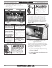
DISCONNECT LATHE FROM POWER before
performing this procedure. Failure to do so
could result in accidental startup, electrical
shock, entanglement or crushing injury, or
property damage.
DO NOT touch hot components. During use,
the clutch and other internal components can
become very hot. Wear heavy gloves or allow
components to cool before service.
Wear safety glasses throughout the entire
procedure. Oil may splash and spring-loaded
components may be thrown, resulting in injury
or loss of vision.
DO NOT rotate the spindle or input pulley by
hand while hands or fingers are inside the
headstock. Doing so may cause entanglement
and serious crushing injuries.
Support components while their mounting
fasteners are being removed. Components may
fall or swing outward if they are not properly
supported, resulting in crushing or laceration
injuries.
Required for Procedure Qty
Wrench 4mm .........................................................1
Another Person .....................................................1
To adjust the spindle clutch:
1. DISCONNECT LATHE FROM POWER!
2. Move the spindle lever to the center (neutral)
position.
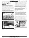
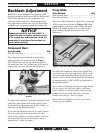
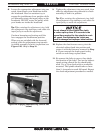
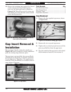
3. Have another person support the electrical
cabinet, then remove the three button-head
cap screws shown in Figure 122.
4. Tilt the cabinet out enough to allow access to
the clutch access cover, being careful not to
strain the lamp or chuck guard safety switch
cords. If necessary, remove these components
to prevent straining them.
Rest the cabinet on a stable support.
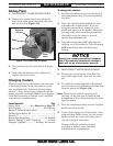
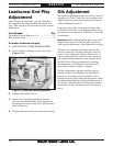
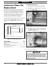
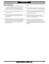
5. Remove the clutch access panel from the rear
of the headstock to expose the dual-clutch
mechanism (see Figure 123).
Figure 122. Removing electrical cabinet fasteners.
Figure 123. Spindle access panel.
Clutch Access
Panel