


1
10
3
4
4
5
6
8
9
7
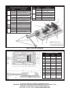
Figure 2. Parts list and diagram.
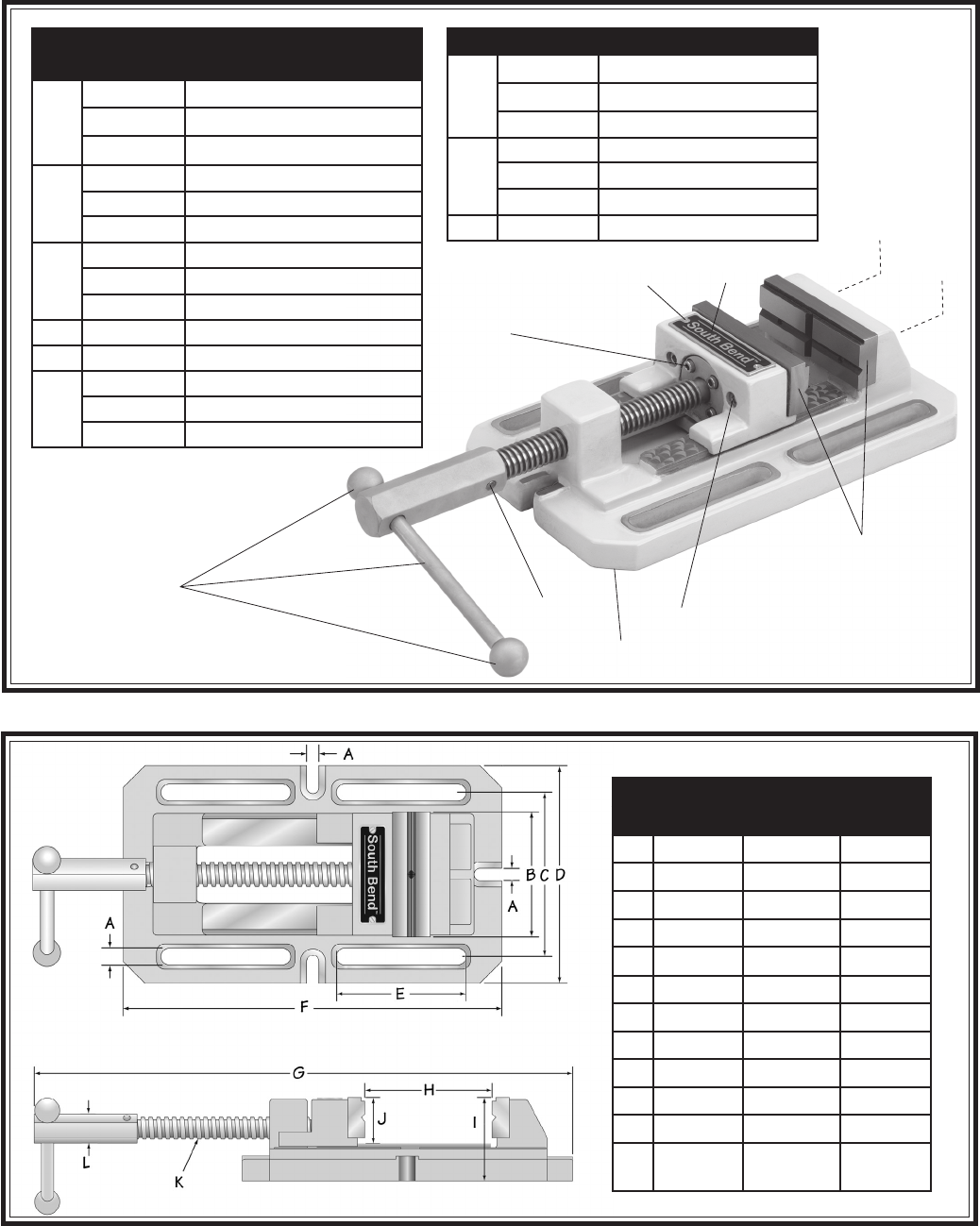
Figure 3. Vise dimensions.
Vise Dimensions Table
SB1215 SB1216 SB1217
A
1
⁄2"
5
⁄8"
5
⁄8"
B
4" 5
1
⁄2" 7
7
⁄8"
C
5
3
⁄8" 7
1
⁄2" 9
7
⁄8"
D
6
3
⁄4" 9
1
⁄8" 11
1
⁄2"
E
4" 4
1
⁄2" 7"
F
11
3
⁄8" 14
7
⁄8" 19
3
⁄16"
G
18
1
⁄2" 24 31
1
⁄2"
H
4
3
⁄8" 6" 8"
I
3" 3
1
⁄2" 4"
J
1
5
⁄8" 2" 2
1
⁄2"
K
4 TPI 5 TPI 6 TPI
L
1"
(25mm)
1
3
⁄16"
(30mm)
1
9
⁄16"
(40mm)
Model: SB1215, SB1216, SB1217 Parts
Item Part# Description
1 PSB1215001 DOWEL PIN 5 X 30MM
PSB1216001 DOWEL PIN 5 X 30MM
PSB1217001 DOWEL PIN 8 X 40MM
3 PSB1215003 NCL CAP SCREW M6-1 X 35
PSB1216003 NCL CAP SCREW M8-1.25 X 40
PSB1217003 NCL CAP SCREW M10-1.5 X 60
4 PSB1215004 NCL CAP SCREW M6-1 X 20
PSB1216004 NCL CAP SCREW M8-1.25 X 20
PSB1217004 NCL CAP SCREW M10-1.5 X 25
5 PSB1215005 NCL CAP SCREW M5-.8 X 10
6 PSB1215006 BRASS SCREW M2-.45 X 5
7 PSB1215007 SB1215 VISE ASSEMBLY
PSB1216007 SB1216 VISE ASSEMBLY
PSB1217007 SB1217 VISE ASSEMBLY
Item Part# Description
8 PSB1215008 SB1215 JAW SET
PSB1216008 SB1216 JAW SET
PSB1217008 SB1217 JAW SET
9 PSB1215009 SB1215 LEVER ASSEMBLY
PSB1216009 SB1216 LEVER ASSEMBLY
PSB1217009 SB1217 LEVER ASSEMBLY
10 PSB1217010 SOUTH BEND LOGO PLATE
Note: Replacement
castings and leadscrew
not available separately.
Copyright © October, 2009 By South Bend Lathe Co.
WARNING: No portion of this manual may be reproduced in any shape or form
without the written approval of South Bend Lathe Co.
#CR12228 Printed in China www.southbendlathe.com