


BR50 User Manual ◄ 11
NOTE:
Partially depressing the trigger allows the tool to run
at slow speed. Slow-speed operation permits easier
starting of the tool bit into the work surface.
5. To start, break an opening (hole) in the center of the
surface. After making a hole, break portions of the
material into the original opening. For best produc-
tivity, the breaking should be done around the origi-
nal hole.
The size of the broken material will vary with the
strength and thickness of the base material and the
amount of any reinforcement wire or rebar.
Harder material or more reinforcing wire or rebar will
require taking smaller bites. To determine the most
effective bite, start with 2 in./50 mm or smaller bites.
Bites can then be gradually increased until the bro-
ken piece becomes too large, requiring increased
time to break off the piece.
Sticking of the tool bit occurs when too large a bite is
being taken and the tool bit hammers into the mate-
rial without the material fracturing. This causes the
tool bit to become trapped in the surrounding mate-
rial.
COLD WEATHER OPERATION
If the breaker is to be used during cold weather, preheat
the hydraulic uid at low engine speed. When using the
normally recommended uid, uid temperature should
be at or above 50 °F/10 °C (400 ssu/82 centistokes) be-
fore use.
Damage to the hydraulic system or breaker can result
from use with uid that is too viscous or thick.
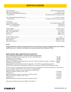
The recommended hose size is .500 inch/12 mm ID up
to 50 ft/15 m long and .625 inch/16 mm ID minimum up
to 100 ft/30 m.
PRE-OPERATION PROCEDURES
CHECK POWER SOURCE
1. Using a calibrated owmeter and pressure gauge,
check that the hydraulic power source develops a
ow of 7–9 gpm/26–34 lpm at 2000 psi/140 bar or
5–6 gpm /18–22 lpm at 1500–2000 psi /105–140
bar.
2. Make certain the hydraulic power source is equipped
with a relief valve set to open at 2250 psi/155 bar
maximum.
INSTALL TOOL BIT
1. Rotate the latch on the breaker foot downward
(pointing away from the tool).
2. Insert the tool bit into the foot and pull the latch up to
lock the tool bit in place.
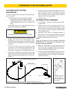
CONNECT HOSES
1. Wipe all hose couplers with a clean, lint-free cloth
before making connections.
2. Connect the hoses from the hydraulic power source
to the tool ttings or quick disconnects. It is a good
practice to connect return hoses rst and discon-
nect them last to minimize or avoid trapped pressure
within the tool.
3. Observe ow indicators stamped on hose couplers
to ensure that uid ow is in the proper direction.
The female coupler on the tool hose is the inlet cou-
pler.
4. Move the hydraulic circuit control valve to the ON
position to operate the tool.
NOTE:
If uncoupled hoses are left in the sun, pressure in-
crease within the hoses may make them difcult to
connect. When possible, connect the free ends of
the hoses together.
OPERATION PROCEDURES
1. Observe all safety precautions.
2. Install the appropriate tool bit for the job.
3. Place the bit rmly on the surface to be broken.
4. Squeeze the trigger to start the breaker. Adequate
down pressure is very important. When the tool bit
breaks through the obstruction or becomes bound,
release the trigger and reposition the tool bit.
OPERATION