


14 ► BR87 User Manual
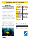
ACCUMULATOR TESTING
PROCEDURE
To check or charge the accumulator the following equip-
ment is required:
31254 Charge Kit: which includes the following.
• Accumulator Tester (Part Number 02835)
• Charging Assembly (P/N 15304)
(P/N 15304 includes a liquid lled gauge with snub
valve, hose and ttings.)
• NITROGEN bottle with an 1000 psi/70 bar minimum
charge. (Not included in 31254 Charge Kit.)
1.
CAUTION
This assembly contains nitrogen under pressure
Remove the valve cap assembly from the breaker.
2. Remove the protective cap and loosen the 5/8-inch
hex locking nut on the tool charging valve 1-1/2
turns.
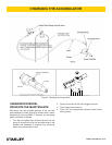
3. Holding the chuck end of Accumulator Tester (P/N
02835) turn the gauge fully counterclockwise to en-
sure that the stem inside the chuck is completely
retracted.
4. Thread the tester onto the accumulator charg-
ing valve. Do not advance the gauge-end into the
chuck-end. Turn as a unit. Seat the chuck on the
accumulator charging valve and hand tighten only.
5. Advance the valve stem of the tester by turning the
gauge-end clockwise until a pressure is read on the
gauge (charge pressure should be 700-900 psi/48-
62 bar).
6. If pressure is OK unscrew the gauge-end from the
chuck to retract the stem, then unscrew the entire
tester assembly from the accumulator charging
valve. If pressure is low, charge the accumulator as
described in the following paragraph.
7. Tighten the 5/8-inch hex locking nut on the tool
charging valve. Be careful not to overtighten. Install
the protective cap and valve cap assembly.
ACCUMULATOR CHARGING
1. Perform steps 1 through 4 of the accumulator test-
ing procedure above.
2. Connect the chuck of the charging assembly to the
charging valve on the accumulator tester or, if pre-
ferred, remove the tester from the charging valve
and connect the charging assembly chuck directly
to the charging valve.
3. Adjust the regulator to the charging pressure of 800
psi/55 bar.
NOTE:
It may be necessary to set the gauge at 850-900
psi/59-62 bar to overcome any pressure drop
through the charging system.
4. Open the valve on the charging assembly hose.
5. When the accumulator is fully charged close the
valve on the charging assembly hose and remove
the charging assembly chuck from the accumulator
tester or tool charging valve.
If the accumulator tester has been used, be sure to
turn the gauge-end fully counterclockwise before re-
moving the tester from the charging valve of the tool.
6. Tighten the 5/8-inch hex locking nut on the tool
charging valve and replace the protective cap.
7. Replace the valve cap assembly.
GENERAL SERVICE NOTES
1. If the breaker is repainted after servicing, be sure to
mask off the vent in the valve cap assembly. Do not
allow paint to enter the IN and OUT ports or the bore
of the foot assembly.
2. If the handle grips need to be replaced.
a. Remove the old grips and clean the handle.
b. Wash the new grips and the handle clean and
dry, simply push or drive the grips on. DO NOT
lubricate the parts. The grips will not be secure
on the handle if any grease or oil is used.
CHARGING THE ACCUMULATOR