


CO23 User Manual ◄ 11
3. Check that the locking mechanism operates prop-
erly to hold the guard in a set position.
WHEEL CONDITION
1. Before installing abrasive wheels, “sound” the wheel
for possible damage by hanging the wheel vertically
by the arbor hole and rapping lightly with a screw-
driver handle or similar instrument. Thin, organic
bond wheels will produce a low drumming tone if it
is physically sound. If the wheel produces a “dead”
or “at” sound, it may be cracked. Cracked or dam-
aged wheels must never be used.
2. Check that the surfaces of the wheel that come in
contact with blotters and anges are free of dirt and
other foreign particles.
3. Check that the correct wheel is used for the job.
4. Check that the wheel conforms to the physical re-
quirements listed in the Specication section of this
manual. The cutoff wheel shall t freely on the drive
ange and remain free under all cutting conditions.
A controlled clearance between the arbor hole and
the cutoff saw drive ange is essential to avoid ex-
cessive pressure from installation and/or arbor ex-
pansion.
5. Check diamond wheels to ensure all seg ments are
intact.
ARBOR AND COLLARS
1. Inspect the drive ange and outer ange prior to in-
stallation. Check for burrs. Check that the bearing
surfaces are at and run true when mounted on the
drive shaft.
2. Inspect the drive shaft threads.
REDUCING BUSHINGS
1. When a reducing bushing is used in the cutoff wheel
mounting hole, check that it does not exceed the
thickness of the wheel.
2. Make sure that the reducing bushing does not pro-
trude beyond the surface of the wheel on both sides.
Bushings that are too thick will not allow the collars
to t properly against the wheel.
3. Check that reducing bushings are tight in the cutoff
wheel mounting hole. Never use bushings that do
not t tightly in the mounting hole. Never use shim
stock.
DRIVESHAFT SPEED CHECK
The speed of the motor output shaft should be checked
at least every 100 hours of operation by trained and
experienced personnel. A record of the speed checks
should be maintained. The maximum rated speed of the
cutoff saw is 3600 rpm. This speed must be equal to or
less than the rated speed of the cutting wheel.
Tests should be conducted while operating the normal
hydraulic power supply used with the cutoff saw.
NOTE:
Excessive speed may be caused by excessive oil
ow to the tool.
OPERATING INSTRUCTIONS
CUTOFF WHEEL INSTALLATION
IMPORTANT
Make sure the wheel has been thoroughly inspected
prior to installation.
NOTE:
When mounting the wheel, use blotters at the col-
lars. The blotters should be made from highly com-
pressible material and should not be more than
0.025-inch/.6 mm thick.
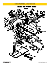
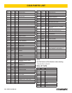
1. Install the wheel on the drive ange. Refer to the
Specication and Parts List sections of this manual
for wheel requirements and parts orientation, re-
spectively.
2. Install the outer ange. (Use the Spirol drive pin on
diamond wheels only.)
3. Install and tighten the wheel nut. Tighten the nut
only tight enough to prevent slippage of the wheel.
4. Adjust the sole plate assembly for proper depth of
cut.
CONNECTING HOSES
1. Wipe all hose couplers with a clean lint-free cloth
before making connections.
2. Connect the hoses from the power supply to the
tool hoses. It is a good practice to connect return
hoses rst and disconnect last to minimize or avoid
trapped pressure within the tool.
3. If hose couplers are used, observe the arrow on the
coupler to ensure that the ow is in the proper direc-
tion. The female coupler on the tool hose is the inlet
coupler.
4. Move the hydraulic circuit control valve to the “ON”
position to operate the tool.
OPERATION