


CO25 User Manual ◄ 11
OPERATION
PREOPERATION PROCEDURES
CHECK THE POWER SOURCE
Careful inspection of the tool and hydraulic system before
startup is important for safe, reliable operation of the tool.
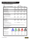
1. Using a calibrated owmeter and pressure gauge, check
that the hydraulic power source develops a ow of 7–9 gpm
(26–34 lpm) at 2000 psi (140 bar).
2. Make certain the hydraulic power source is equipped
with a relief valve set to open at 2100–2250 psi (145–155
bar).
CHECK THE TOOL
The following items should be checked daily.
Make sure the hydraulic system control valve is in the
“OFF” position and the hoses are disconnected before
inspecting the cutoff saw.
1. Inspect the cut-off wheel and guard. Make sure the cor-
rect cut-off wheel is installed for the job. If not, follow the
instructions for Cut-off Wheel Replacement section of this
manual.
2. Inspect the wheel for chips, cracks, or other damage. For
maximum tool performance, replace the wheel if it is worn
or defective.
3. Inspect the wheel guard for cracks or other structural
damage.
4. There should be no signs of leaks.
5. Inspect the handlebar. Make sure the handlebar is se-
curely fastened to the cutoff saw and is clean of any oil to
ensure a rm grip.
Check the speed of the motor output shaft after every
100 hours of operation.
CHECK TRIGGER MECHANISM
1. Inspect the trigger and safety catch. Make sure the trig-
ger operates smoothly and is free to travel between the
“ON: and “OFF” positions.
2. Make sure the trigger is set to disengage the cut-off saw
when released.
3. Check that the safety catch on the handle assembly is
operating properly. It should prevent engagement of the
trigger unless the catch is pressed down fully in the handle
slot.
CONNECT HOSES
1. Wipe all hose couplers with a clean, lint-free cloth before
making connections.
2. Connect hoses from the hydraulic power source to the
tool ttings or quick disconnects. It is good practice to con-
nect the return hose rst and disconnect it last to minimize
or eliminate trapped pressure within the wrench.
3. Observe the ow indicators stamped on the valve handle
assembly and the hose couplers to ensure that the ow is
in the proper directions. The female couple on the tools “IN”
port is the inlet (pressure) coupler.
Note:
If the uncoupled hoses are left in the sun, pressure
increase within the hoses can make them difcult to
connect. Whenever possible, connect the free ends of
hoses together.
TOOL OPERATION
STARTUP
1. Move the hydraulic system control valve to the “ON”
position.
2. At the beginning of each shift, or after a new wheel is
installed, run the cut-off saw at operating speed for at least
one minute before starting work.
HANDHELD CONFIGURATION:
1.Press the safety catch into the handle, then slowly
squeeze the trigger.
2. Run the saw at least one minute.
3. Release the trigger and safety catch.
MOUNTED CONFIGURATION (SAW CART):
1. Make sure the lower edge of the cutoff wheel is at least 1
inch above the work surface.
2. Slowly squeeze the hand control lever.
3. Run the saw at least one minute, then release the control
lever.
IMPORTANT