


10 ► HD45 User Manual
OPERATION
PREOPERATION PROCEDURES
CHECK POWER SOURCE
1. Using a calibrated owmeter and pressure gauge,
check that the hydraulic power source develops a
ow of 7-9 gpm/26-34 lpm at 1500-2000 psi/105-
140 bar.
2. Make certain that the hydraulic power source is
equipped with a relief valve set to open at 2250
psi/155 bar.
CHECK THE TOOL
1. Make certain all tool accessories are correctly in-
stalled. Failure to install tool accessories properly
can result in damage to the tool or personal injury.
2. There should be no signs of leaks.
3. The tool should be clean and dry with all ttings and
fasteners tight.
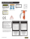
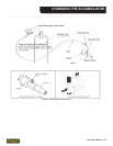
BIT INSTALLATION
The hammer drill is designed for use with 1-inch to
2-inch diameter bits manufactured for Model 736 Skil
Hex Hammer Drills.
1. Pull the latch at the foot of the tool so that the drill
can be inserted into the drive hex.
2.
WARNING
Do not allow your ngers to come between the latch
and drill steel when closing the latch.
Push the latch back into the “latched” (vertical) posi-
tion to lock the bit in place.
CONNECT HOSES
1. Wipe all hose couplers with a clean lint-free cloth
before making connections.
2. Connect the hoses from the hydraulic power source
to the tool ttings or quick disconnects. Connect the
return hose rst and disconnect it last to eliminate
or reduce trapped pressure for easier quick-connect
tting attachment.
NOTE:
If uncoupled hoses are left in the sun, pres sure in-
crease within the hoses can make them difcult to
connect. Whenever possible, connect the free ends
of hoses together.
3. Observe the ow indicators stamped on the hose
couplers to ensure that the ow is in the proper di-
rection. The female coupler on the tool’s “IN” port
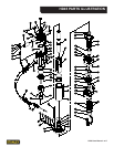
is the inlet coupler. See illustration in back of this
manual for tool port identication.
4. Squeeze the drill trigger momentarily. If the drill does
not operate, the hoses might be reversed. Verify
correct connection of the hoses before continuing.
DRILL OPERATION
1. Observe all safety precautions.
2. Install the appropriate drill bit for the job.
NOTE:
The rotation of the drill bit is reversible. Drill bit
speed is variable in each direction. This is accom-
plished by rotating the lever on the lower section of
the tool. The tool is in neutral when the lever is in the
vertical “up” position. The lever can be rotated 90°
to the “horizontal” position in each direction. (The
direction that the bit rotates.) The distance that the
lever is rotated determines the speed of the bit. The
horizontal position in either direction is the maxi-
mum speed setting.
3. Select the speed of the bit best suited for the mate-
rial being drilled. Most drilling is best accomplished
with the lever halfway between fully “On” (horizon-
tal) and the vertical “up” position. Refer to the above
note. The drill is not suitable for drilling steel or wood.
4. Squeeze the trigger to start the drill. Adequate down
pressure is very important.
NOTE:
If the trigger is partially depressed, the piston will
cycle at a low rate and permit easier starting of the
drill bit into the work surface.
5. Periodically pull the drill out of the hole while the
bit is still rotating. This will clear the hole and allow
more efcient penetration.
6. If the bit binds in the hole, reverse direction of the bit
rotation to assist in “backing out” the drill.
7. Keep the drill bit centered in the hole.