


these switches divide the battery charger
INSTALLATION OF
amp/hr into the battery bank size (
STERLING BATTERY
domestic bank ) e.g take a 25 amp charger
CHARGER
on a 200 amp hr battery bank = a ratio of
8 : 1 . if the ratio is between 1-4:1 leave
Position the charger in a cool dry well
all switches on and the equalizing time
ventilated space, ensuring a reasonable
will be approx 1hr, with a ratio of 5-9: 1
air flow around the charger ( do not
switch no 1 switch off, and this will
install in a cupboard or sealed
increase the equalizing time to about
compartment.
2hrs, with a ratio of 10-13: 1 switch nos 1
and 2 to the off position this will increase
the time to 3 hours, with a ratio of 14 - 18:
1 switch 1 2 and 3 to the off position,
this will increase the equalizing time to
about 4 hrs.or set up as per label hints.
install as close to the batteries as
possible, preferably within 2 meters of
the batteries.
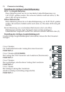
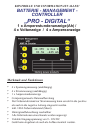
Before installing, the charger must be
set up. beside the output terminals one
Having set the battery type switch and the
can see two sets of switches under the
equalizing time switches the charger
terminals, a switch bank of 3 small
should be installed, and need only be
switches and a large single switch.
altered in the event of a battery type
the large switch ( s1 ) changes the
change or battery bank size change.
equalizing or bulk charge voltage from
14.4 - 14.8 volts ( 28.8 - 29.6 for 24
The charger may be mounted in any
volt units ) the 14.4 volt position must
position . in the interests of safety connect
be used if gel or sealed lead acid
the cables to the charger and run them to
batteries are used on any bank ( always
the batteries, the correct cable to use is
avoid gel or sealed batteries for heavy
multi strand automotive type cable. each
cycling ), the 14.8 volt position should
strand is suitable to carry 1/2 an amp over
be used for conventional ventilated
about 2 meters, ie a 30 amp charger would
lead acid batteries and traction
require 50 strand copper cable.
batteries. if in doubt go for the 14.4
volt position,
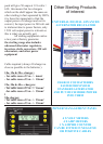
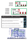
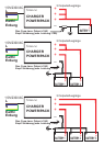
Connect the cables as per the diagram,
The switch in the down position
ensure that all terminals are used, ie in the
confirmed by the top l.e.d being
event of only one battery being charged
yellow is suitable for standard lead
then connect the surplus positive output to
acid or traction batteries ( 14.8 volts/
the other used output, ie both outputs are
29.6 volts ) not suitable for gel or
on the same battery.
sealed batteries.
the small set of three switches changes
the time of the equalizing charge by
approx 1 hr per switch, in order to set
This unit is fitted with an automatic
110/230 volt crossover as such the
following voltage may be used ( 80-
130 or 170-280 volts at any
frequency ( 40-400 hz )
if
in doubt set to the standard setting as per
the label covering the output battery
terminals.
It is extremely important to join any
output terminal not being used on to one
which is in use , ie if only 2 outputs are to
be used then the third must be joined on