


common
negative
domestic
battery
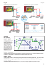
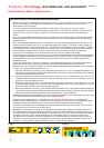
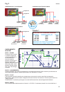
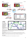
Installation for 1 battery bank
link
link
battery timer control
battery type control
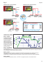
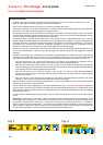
4 STEP CHARGE
STEP 1 - BOOST:
During this stage the
charger supplies a
maximum current and
the voltage increases
progressively according
to the battery type
selected. This step
depends on the initial
state of the batteries.
The “Fast Charge” LED
is on.
STEP 2 - ABSORPTION:
This is an adjustable
period during which the voltage is kept at its maximum and the current decreases in order to optimise the battery
charge. The “Absorption” LED is on.
STEP 3 - FLOAT:
The voltage is kept at float level in order to maintain the charge without increasing the temperature of the
batteries. They can be left connected without any damage. The “Float” LED is on.
POWERPACK function: Full current is available for on-board supply.
STEP 4 - RESET:
If the battery voltage goes down below 11.5V/23.0V, then the charge cycle starts all over again with step 1.
Fig. 3
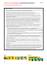
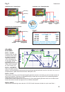
Installation for 2 battery banks
domestic
battery
engine
start battery
common
negative
battery timer control
battery type control
English
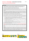
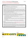
Installation for 3 battery banks
domestic
battery
engine
start battery
common
negative
bow thruster
battery
battery timer control
battery type control
Adjustable
3
link
Cable Size Recommendation:
Charger Output Cable Length 0 - 1.5 mtr 1.5 - 4 mtr
Important: Two 35 sq mm cables in parallel are
equivalent to a single 70 sq mm cable.
25-45 amps 16 sq mm 25 sq mm
45-85 amps 25 sq mm 35 sq mm
85-125 amps 35 sq mm 50 sq mm
125- 180 amps 50 sq mm 70 sq mm
180-330 amps 70 sq mm 90 sq mm
0-25 amps 6 sq mm 10 sq mm
Table 1
Sterling fuseholder
GMFB-4848
(not included)