


STUDER INNOTEC
COMPACT
COMPACTCOMPACT
COMPACT
User manual COMPACT V2.0 E 13
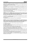
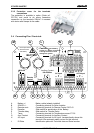
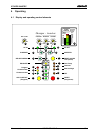
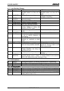
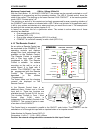
4.2 Light Emitting Diodes:
LED Marking LED lit LED blinks
1 AC IN Voltage corresponding to self-
adjusted values is at the AC IN
input.
Voltage, outside of the self-
adjusted values is at the AC IN
input.
2 CHARGER Battery Charger is working The input voltage is out value
(voltage or frequency)
3 SOLAR
CHARGE
Connected Solarmodules are
delivering energy
4 Program Program mode for Aux. Contact
5 Contact active Auxiliary Contact is activated
6 Contact manual Aux. Cont. manually activated
7 Transfersystem is active. In-
coming voltage is being sent
directly to AC OUT outlet
8 AC OUT There is voltage at the AC OUT
outlet
The Inverter is in Standby-Mode
9 INVERTER Inverter is working Forced -Inverter Mode
10 Over Temp. For the time being the COMPACT
is out of service because of
overheating.
11 Overload The COMPACT is out of service
because of overload or short-
circuit
12 Batt. Low/High Battery voltage is too low Battery voltage is too high
13 OFF COMPACT is turned off. Turning it
back on is only possible manually.
COMPACT is for the time being
turned off. Turning it back on will
follow automatically!
14 Battery Charger and or Solar
Charge Regulator are doing an
equalization cycle
15–18 Charge condition of Battery LED 15 – Absorbtion time is
running
25 CURRENT
MONITOR
Display the value of the output power in % of Pnom (in Inverter Mode)
and the charge current in Amps. (in Charger Mode) In this mode the
200% LED indicate that power sharing is in use.
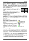
4.3 Push buttons:
19 ON/OFF Turning the COMPACT on and off (Help Button for Programming)
20 RESET Alarm Signal off (Help Button for Programming)
21 Aux. Contact Control Aux. contact (Help Button for Programming)
4.4 Turning Knobs:
22 CHARGER Adjustment for max. Charging Current (Not for Solar charge regulator)
23 TRANSFER Adjustment for Transfer Voltage Threshold(TRANSFER – INVERTER)
24 STANDBY Adjustment for „Standby“ system
26 INPUT LIMIT Must be adjusted to the maximal available current of your AC INPUT
supply (see on chap.
4.6.3)