STUDER INNOTEC HP-COMPACT
User manual HP-COMPACT V3.0 E 23
As per the inverter output power (not available with some special executions)
Activating the auxiliary contact for the generator start can be programmed also on a pre-
determined output power of the inverter. The auxiliary contact will be activated if the in-
verter output power exceeds 80% of the inverter nominal power during 3 minutes and/or
100% during 30 seconds.
The auxiliary contact will remain activated 30 minutes after the input current has come
back to a value lower than the one adjusted by the “INPUT LIMIT” (chap. 4.6.3). In other
words, the contact will be deactivated 30 minutes after the lighting out of the LED 200%.
This programming is achieved accordingly to chap. 5.4.2 of the user manual and by acti-
vating the contact on LED 100% of “Power Monitor” (25).
5.4.4 Power cut of the second priority loads
The auxiliary contact can also be used to cut the power of less priority loads when the bat-
tery state of charge is lower than a given threshold. In that case, only one of the battery
state of charge, or the “transfer” function will be programmed as power cut criteria.
The second priority loads will be supplied only when the genset is ON or when the battery
has a sufficient threshold.
5.4.5 Manual operating of Auxiliary Contact
The Auxiliary Contact can be operated at any time with the Push Button 21 (AUX. CON-
TACT). The LED 6 „Contact manual“ lights up as information that the Contact is manually
operated, and LED 5 „Contact active“ lights up when the Contact is active. By pushing the
Push Button 21 a second time, the Contact is disabled. By pushing it the third time, auto-
matic functions are restored.
5.5 Disabling some of the HP-COMPACT functions
Each different function charger, inverter and transfer can be disabled. This is useful for
specific applications witch required to disable some of these three functions.
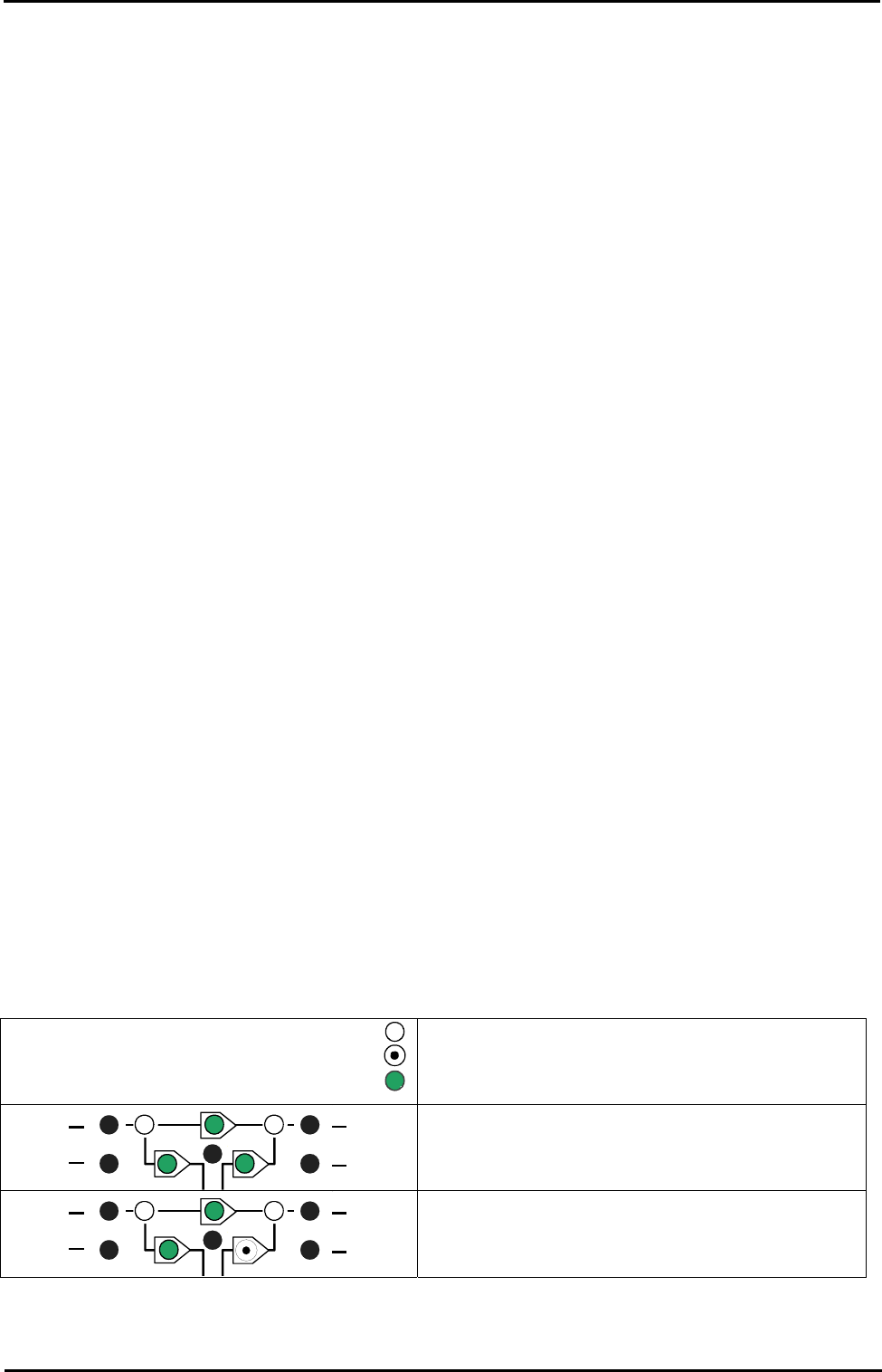
If you press the button (20) more than 2 seconds you can have access to the different
possibilities shown in the following diagram.
In programming mode the display shows only the different types of program with the three
LED’s 2, 7 and 9 to each function. To change the type of programming, press shortly the
button 20 until you reach the right function used according to the table below. After 20
seconds the HP-COMPACT exits the programming mode and loads the new change.
In user mode, the disabled functions are displayed by blinking LED. So you can see which
mode is disabled.
5.5.1 Diagram of the different modes
9
Shows an off LED
Shows a blinking LED
Shows a lighted LED
CHARGER
INVERTER
AC OUTAC IN
1
2
7
8
9
All the functions are enabled. This is the fac-
tory setting.
CHARGER
INVERTER
AC OUTAC IN
1
2
7
8
9
The inverter is disabled. Only the transfer
switch and the charger will work normally.


