


STUDER INNOTEC HP-COMPACT
User manual HP-COMPACT V3.0 E 16
DANGER OF AN EXPLOSION !! The battery room must be well ventilated.
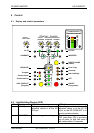
4.6.3 Input current repartition (Power sharing)
To manage the power available on the AC INPUT (depends on the supply use) the HP-
COMPACT is equipped with a system usually called “Power sharing” or INPUT power dis-
tribution. With this function it is possible to limit the AC INPUT current assigned to the
charger. The more current it uses on the OUTPUT the less it gives to the charger. Priority
to the OUTPUT. When the power sharing is used the LED 200% (red) is lit to point out that
the charge is limited.
Caution: if the power use on the OUTPUT is higher than the value of the INPUT LIMIT (26)
the HP-COMPACT cannot limit the current, then the generator means to stop or the circuit
breaker means to break before.
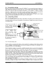
4.6.3.1 Set the INPUT LIMIT (26)
The current available for the HP-COMPACT depends on the
supply used from a motor generator, the network of a camp-
ing or of a shore connection. The value of the turning knobs
INPUT LIMIT (26) must be adjusted lower or equal to the cur-
rent available from the source.
For example if you have a generator of 2kW you must adjust
the turning knobs 26 to a max. 8.5A. To calculate this, one
divides the nominal power (2000W) by the voltage (230V). If
you have a circuit breaker (i.e. 6A) before the HP-COMPACT,
then you set this value on the turning knobs (26) (i.e. 6A).
This adjustment can be done remotely with the optional RPS-01 (see section 3.6.7). In that
case the smallest values will be taken into account.
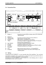
4.6.4 Charging current
The maximum charging current for the battery can be adjusted with the Turning Knob 22
(CHARGER). The charging current of the battery should be set to approximately 10 – 20%
of the battery capacity (at C10). This means that the charging current for a battery with
300Ah should be set between 30 – 60A.
The charging current is displayed on POWER MONITOR (25) of the front panel or on the
Remote Control.
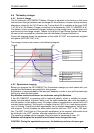
4.6.5 Battery Condition
Built-in microprocessor with a specially developed algorithm calculates the actual state of
charge of the battery and displays it on LED 15 – 18. The LED 14 is lit when the system is
carrying out a charge cycle with equalization.
Notice: the exact measure of the battery state of charge with electrical parameters is al-
most impossible. The display of the state of charge is always more or less precise. The
measure system built in the HP-COMPACT takes into account the battery voltage, the dis-
charge and charge current as well as the undulation of the voltage. If the battery and the
HP-COMPACT are used according to their technical data, the battery state of charge is
displaid accurately. In the following cases of use the display can diverge:
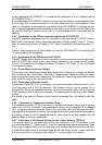
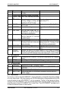
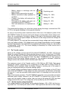
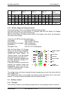
Generator
power
Current
(230V)
500W 2A
900W 4A
1500W 6.5A
2000W 8.5A
3000W 13A
5000W 21A