


STUDER INNOTEC
XP-COMPACT
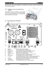
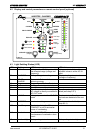
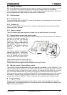
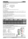
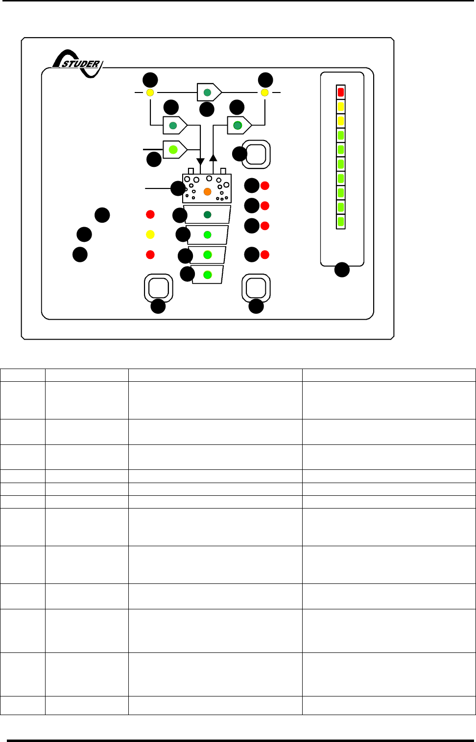
4.2 Display and control parameters on remote control panel (optional)
160
OFF
AC OUT
Over Temp.
Overload
AC IN
SOLAR CHARGE
Contact manual
Contact active
Program
COMPACT
AUXILIARY CONTACT
ON/OFF
INVERTER - CHARGER
(Select)
RCC-01
INVERTERCHARGER
(Program) (Change status)
Battery
Low/High
RESET
ALARM
10
20
30
40
50
60
70
80
90
100
TRANSFER
Charger
Inverter
5
10
20
40
60
80
100
130
160
A %
EQUALIZE
1
15
16
17
18
19
2
3
21
4
5
6 13
12
11
10
20
25
8
7
9
14
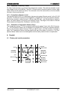
4.3 Light Emitting Diodes (LED)
LED Marking LED lit LED blinks
1 AC IN Voltage at the AC IN input is within
the accepted range (voltage and
frequency)
Voltage, outside of the self-
adjusted values is at the AC IN
input.
2* CHARGER Battery Charger is working The input voltage is out value
(voltage or frequency)
3 SOLAR
CHARGE
Connected Solar modules are
delivering energy
4* Program Program mode for Aux. Contact
5* Contact active Auxiliary Contact is activated
6* Contact manual Aux. Cont. manually activated
7 Transfer system is active. Input
AC voltage is directly connected to
AC OUT outlet
Transfer system (by-pass) is dis-
abled (see chap. 6.5.1)
8 AC OUT Voltage is present at the AC OUT
outlet
The Inverter is in Standby mode.
No loads are detected at the out-
put
9* INVERTER Inverter is working Inverter mode is disabled (see
chap. 6.5.1)
10* Over Temp. For the time being the XP-
COMPACT is out of service be-
cause of overheating.
11* Overload The XP-COMPACT is out of ser-
vice because of overload or short-
circuit
12 Batt. Low/High Battery voltage is too low Battery voltage is too high
User manual XP-COMPACT V2.0 E
11