


BEFORE INSTALLING
This information is included as a quick reference installation
guide. Refer to the appropriate control panel installation manual
for detailed system information. If the modules will be installed
in an existing operational system, inform the operator and local
authority that the system will be temporarily out of service.
NOTICE: This manual should be left with the owner/user of
this equipment.
GENERAL DESCRIPTION
Relay Module, Model EM-1RI, is to be designed for use in activa-
tion of the types of products that are generally connected to an in-
telligent fire alarm system. It provides two sets of form C contacts
that switch together (one DPDT relay). There is also an input that
is capable of monitoring a dry set of contacts for open or closed
conditions. The module also has on-board short circuit isolators
to prevent shorts on the signaling line circuit from disabling more
than one device on the intelligent loop.
COMPATIBILITY REQUIREMENTS
To ensure proper operation, this module shall be connected to a
listed compatible control panel.
D500-61-00 1 I56-2023-004
3825 Ohio Avenue, St. Charles, Illinois 60174
1-800-SENSOR2, FAX: 630-377-6495
www.systemsensor.com
EM-1RI Relay Module
SPECIFICATIONS
Normal Operating Voltage: 15 to 30 VDC
Standby Current: 500 µA max. average (continuous broadcasts)
Alarm Current: 2.0 mA (red LED on)
Short Circuit Current
Dry Control Input: 30 µA max. Avg. (5VDC)
Maximum Resistance
Dry Contact Input: 100
Ω
Temperature Range: 32°F to 120°F (0°C to 49°C)
Humidity: 10 to 93% RH Non-condensing
Dimensions: 4.17˝ H x 4.26˝ W x 1.22˝ D
(106 mm H x 108 mm W x 31 mm D)
Accessories: Wall cover plate (included)
SMB500 Surface Mount Electrical Box
CB500 Control Module Barrier
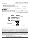
LED
INDICATOR
IR
RECEIVER
C0166-00
MOUNTING
The module mounts directly to 4˝ square electrical boxes. The box
must have a minimum depth of 2
1
⁄8˝. Modules must be mounted
with the arrow facing upward for proper operation of the IR pro-
gramming tool. Surface mounted electrical boxes (SMB500) are
available from System Sensor.
INSTALLATION AND MAINTENANCE INSTRUCTIONS
NOTE: This module is not approved for use in the European Union, at or above 50VAC or 70VDC.
I56-2023-004
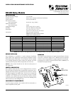
CURRENT RATING MAXIMUM VOLTAGE LOAD DESCRIPTION APPLICATION
3 A 30 VDC Resistive Non-Coded
2 A 30 VDC Resistive Coded
.9 A 110 VDC Resistive Non-Coded
.9 A 125 VDC Resistive Non-Coded
.5 A 30 VDC Inductive (L/R=5ms) Coded
1 A 30 VDC Inductive (L/R=2ms) Coded
.3 A 125 VAC Inductive (PF=.35) Non-Coded
1.5 A 25 VAC Inductive (PF = .35) Non-Coded
.7 A 70.7 VAC Inductive (PF=.35) Non-Coded
2 A 25 VAC Inductive (PF=.35) Non-Coded