


In order to control which devices are addressed first in wiring
configurations with branches, a branch marker can be set at a
particular device. A branch marker is an electronic value from 0 to
255 stored in the device memory. The branch markers are set with
the IR configuration tool, EA-CT.
TERMINAL DEFINITIONS
T1 (+) SLC in/out T7 Normally Closed #1
T2 (–) SLC in/out T8 Common #1
T3 (+) SLC in/out T9 Normally Open #1
T4 (–) SLC in/out T10 Normally Closed #2
T5 (+) Dry Contact Input T11 Common #2
T6 (–) Dry Contact Input T12 Normally Open #2
WARNING
All relay switch contacts are shipped in the standby state (open)
state, but may have transferred to the activated (closed) state dur-
ing shipping. To ensure that the switch contacts are in their cor-
rect state, modules must be made to communicate with the panel
before connecting circuits controlled by the module.
This device complies with part 15 of the FCC Rules. Operation is subject to the following two conditions: (1) This device may not cause harmful interference, and (2) this device
must accept any interference received, including interference that may cause undesired operation.
NOTE: This equipment has been tested and found to comply with the limits for a Class B digital device, pursuant to Part 15 of the FCC Rules. These limits are designed to pro-
vide reasonable protection against harmful interference in a residential installation. This equipment generates, uses and can radiate radio frequency energy and, if not installed
and used in accordance with the instructions, may cause harmful interference to radio communications. However, there is no guarantee that interference will not occur in a
particular installation. If this equipment does cause harmful interference to radio or television reception, which can be determined by turning the equipment off and on, the user
is encouraged to try to correct the interference by one or more of the following measures:
– Reorient or relocate the receiving antenna.
– Increase the separation between the equipment and receiver.
– Connect the equipment into an outlet on a circuit different from that to which the receiver is connected.
– Consult the dealer or an experienced radio/TV technician for help.
FCC Statement
D500-61-00 2 I56-2023-004
©2006 System Sensor
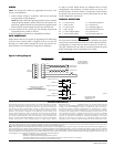
Figure 2: Wiring Diagram
FROM PANEL OR
PREVIOUS PANEL
(–)
(+)
SIGNAL LINE CIRCUIT (SLC)
30 VDC MAX.
TWISTED PAIR RECOMMENDED
SIGNAL LINE CIRCUIT (SLC)
IS SUPERVISED AND
POWER LIMITED
(–)
(+)
(–)
(+)
(–)
(+)
1
2
3
4
TO NEXT DEVICE
5
6
12
11
10
9
8
7
{
RELAY
CONTACTS
NOTE: NORMALLY OPEN
OR NORMALLY CLOSED
CONTACT DEVICE
(NOT SUPERVISED)
NOTE: NORMALLY CLOSED
OPTION MAY NOT BE USED
FOR FIRE APPLICATIONS.
CONNECT MODULES
TO LISTED COMPATIBLE
CONTROL PANELS ONLY
NORMALLY OPEN (T12)
COMMON (T11)
NORMALLY CLOSED (T10)
NORMALLY OPEN (T9)
COMMON (T8)
NORMALLY CLOSED (T7)
RELAY
CONTACT #2
RELAY
CONTACT #1
MODULE DOES NOT SUPERVISE
CONTROLLED CIRCUITS.
TERMINALS 1-6 ARE POWER LIMITED.
TERMINALS 7-12 ARE NON-POWER LIMITED.
System Sensor warrants its enclosed module to be free from defects in materi-
als and workmanship under normal use and service for a period of three years
from date of manufacture. System Sensor makes no other express warranty for
this module. No agent, representative, dealer, or employee of the Company
has the authority to increase or alter the obligations or limitations of this
Warranty. The Company’s obligation of this Warranty shall be limited to the
repair or replacement of any part of the module which is found to be defective
in materials or workmanship under normal use and service during the three
year period commencing with the date of manufacture. After phoning System
Sensor’s toll free number 800-SENSOR2 (736-7672) for a Return Authorization
number, send defective units postage prepaid to: System Sensor, Returns
C0110-02
WIRING
NOTE: All wiring must conform to applicable local codes, ordi-
nances, and regulations.
1. Install module wiring in accordance with the job drawings
and appropriate wiring diagrams.
NOTE: Separate cable entry openings must be used to maintain
required spacing between power limited and non-power lim-
ited wiring. Optional EA-CB may be required to separate power
limited and non power limited wiring in the electrical box.
2. Set the address on the module per job drawings using the IR
configuration tool (model no. EA-CT).
3. Secure module to electrical box (supplied by installer).
AUTO ADDRESSING
Eclipse Series devices are capable of supporting auto addressing,
if the fire alarm control panel is designed to do so. In auto ad-
dressing, the control panel, through the use of each device’s on-
board isolators, can automatically assign device addresses.
Three-Year Limited Warranty
Department, RA #__________, 3825 Ohio Avenue, St. Charles, IL 60174. Please
include a note describing the malfunction and suspected cause of failure. The
Company shall not be obligated to repair or replace units which are found to
be defective because of damage, unreasonable use, modifications, or altera-
tions occurring after the date of manufacture. In no case shall the Company
be liable for any consequential or incidental damages for breach of this or any
other Warranty, expressed or implied whatsoever, even if the loss or damage
is caused by the Company’s negligence or fault. Some states do not allow the
exclusion or limitation of incidental or consequential damages, so the above
limitation or exclusion may not apply to you. This Warranty gives you specific
legal rights, and you may also have other rights which vary from state to state.