


©Titan Tool Inc. All rights reserved. 23
Accessories
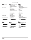
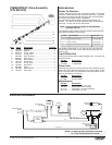
Airless Tip Selection
Tips are selected by the orifice size and fan width. The proper
selection is determined by the fan width required for a specific
job and by the orifice size that will supply the desired amount
of fluid and accomplish proper atomization.
For light viscosity fluids, smaller orifice tips generally are
desired. For heavier viscosity materials, larger orifice tips are
preferred. Please refer to the chart below.
The following chart indicates the most common sizes and the
appropriate materials to be sprayed.
Fan widths measuring 8" to 12" (20 to 30 cm) are preferred
because they offer more control while spraying and are less
likely to plug.
Liquid Shield Plus
Cleans and protects spray systems against rust, corrosion and
premature wear.
Part No.
Description
314-483...........4 ounce bottle
314-482...........1 quart bottle
Piston Lube
Specially formulated to prevent materials from adhering to the
piston rod, which becomes abrasive to the upper seals. Piston
Lube will break down any material that may accumulate in the
wet cup and keep it from drying.
Part No.
Description
314-481...........4 ounce bottle
314-480...........8 ounce bottle
Miscellaneous
Part No. Description
490-012...........Hose coupling, 1/4" x 1/4"
730-397...........High pressure fluid Gauge
314-171...........Lubriplate, 14 ounce individual
314-172...........Lubriplate, 6 lb. can
Tip Size Spray Material Filter Type
.011 — .013 Lacquers and stains 100 mesh filter
.015 — .019 Oil and latex 60 mesh filter
.021 — .026 Heavy bodied latex and blockfillers 30 mesh filter
NOTE: Do not exceed the sprayer's recommended
maximum tip size.
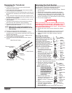
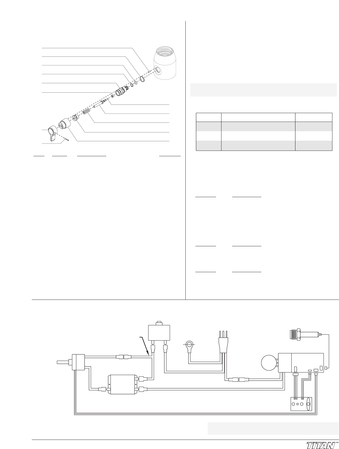
Electronic
Control Assy
Indicator Lights
Assembly
800-278
BLACK/RED/WHITE
BLACK
RED
WHITE
BLUE/YELLOW
GRAY/PURPLE
Transducer
800-449
BLACK
WHITE
WHITE
WHITE
BLACK
BLACK
BLACK
ORANGE
ORANGE
GREEN
Wire Assembly
800-368
Ground to
Gear Housing
Circuit
Breaker
765-327
Plug
Relay
800-276
Potentiometer Assy
800-277
Motor
Electrical Schematic
NOTE: All electrical work should be performed
by a Titan authorized service center.
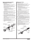
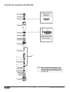
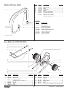
PRIME/SPRAY Valve Assembly
(P/N 800-915)
Item Part # Description Quantity
1 700-823 Dowel pin....................................................1
2 700-537 Gasket ........................................................1
3 222-012 O-ring, Teflon ..............................................1
4 221-012 O-ring, Viton................................................1
5 700-253 Valve housing .............................................1
6 800-910 Valve seat ...................................................1
7 700-697 Valve handle ...............................................1
8 700-759 Groove pin ..................................................1
9 700-721 O-ring, Viton................................................1
10 700-250 Valve stem ..................................................1
11 800-926 Spring .........................................................1
12 700-248 Valve retainer..............................................1
13 700-251 Cam base ...................................................1
1
2
3
4
5
6
7
8
9
10
11
12
13