6
1. Overview and Features
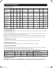
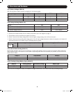
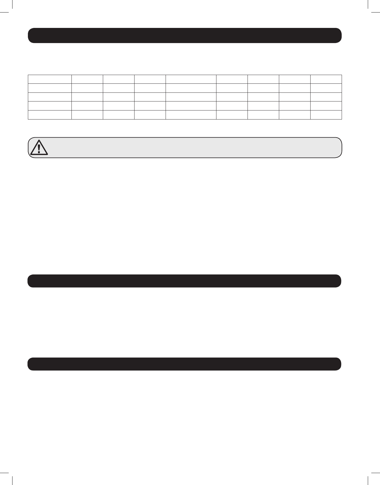
1.2.11 Battery Charging Rate Setting (Switch 6, 7 & 8)
These switches control the maximum charging rate in amps. The charge rate has 8 stages. It can be adjusted by setting these
switches as shown in the following table:
Switch 6
ON ON ON ON OFF OFF OFF OFF
Switch 7
ON ON OFF OFF ON ON OFF OFF
Switch 8
ON OFF ON OFF ON OFF ON OFF
APSX1012SW
40A 32A 24A 20A (Default) 16A 12A 8A 4A
APSX2012SW
60A 48A 36A 30A (Default) 24A 18A 12A 6A
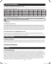
Note: The charging rate depends on the battery bank size. Consult the battery manufacturer’s specs for the maximum allowed
charge rate (usually 0.3 times the AH rating).
Caution! An excessively high charging rate can overheat the battery. If a small-capacity battery is
used, set the battery charge rate to the minimum setting.
1.3 Features
1.3.1 Battery Temperature Port
This port allows connection of a Battery Temperature-Sensing Cable (sold separately). The sensing function prolongs battery
life by adjusting the charge oat voltage level based on battery temperature. Connect the sensor cable to the RJ11 port
labeled “Battery Temperature.” With user-supplied electrical or duct tape, secure the sensor to the side of the battery below
the electrolyte level. Make sure that nothing, not even tape, comes between the sensor and the side of the battery. To guard
against false readings due to ambient temperature, place the sensor between batteries if possible and away from sources of
extreme heat or cold. If the sensor cable is not used, the Inverter/Charger will charge according to its default 25°C values.
1.3.2 Communication Port (for APSRMSW Remote Control)
This port allows connection of the APSRMSW Remote Control (sold separately). The remote conrol allows the Inverter/
Charger to be mounted out of sight in a compartment or cabinet and operated conveniently from a remote location. See the
instructions packed with the remote control module for more information.
2. Battery Charger
2.1 Mode of Operation
The internal battery charger and automatic transfer relay allow the unit to operate as either a battery charger or an inverter. An
external AC power source (e.g. shore power or generator) must be connected to the inverter’s AC input in order to allow it to
operate as a battery charger. When the unit is operating as a charger, AC loads are powered by the external AC power source.
2.2 Transfer Switching Speed
Transfer time is less than 16 milliseconds.
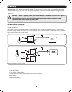
3. Battery
3.1 Select Battery Type
Select 12V “Deep Cycle” batteries to receive optimum performance from your Inverter/Charger. Do not use ordinary car or
starting batteries or batteries rated in Cold Cranking Amps (CCA). If the batteries you connect to the Inverter/Charger are not
true Deep Cycle batteries, their operational lifetimes may be signicantly shortened. If you are using the same battery bank to
power the Inverter/Charger as well as DC loads, your battery bank will need to be appropriately sized (larger loads will require a
battery bank with a larger amp-hour capacity) or the operational lifetimes of the batteries may be signicantly reduced.
Batteries of either Wet-Cell (vented) or Gel-Cell /Absorbed Glass Mat (sealed) construction are ideal. Set Switch 5 to OFF for
Wet-Cell batteries and ON for Absorbed Glass Mat (AGM) batteries. Two 6-volt “golf cart”, Marine Deep-Cycle or 8D Deep-
Cycle batteries in series are also acceptable. In many cases, the vehicle battery may be the only one installed. Auxiliary
batteries must be identical to the vehicle batteries if they are connected to each other.
201110117 93-3054.indb 6 11/9/2011 10:57:55 AM


