


3PV
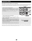
Feature Identification
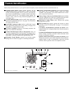
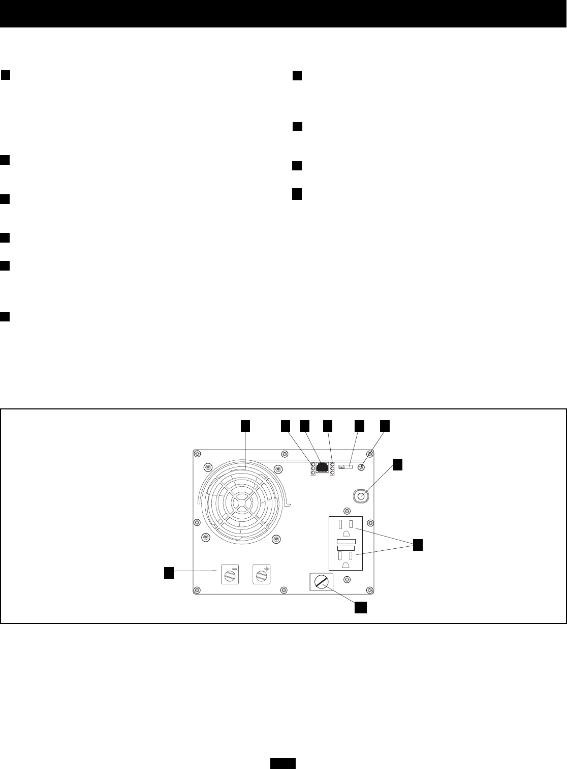
Identify the premium features on your specific model and quickly locate instructions on how to maximize their use.
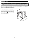
Operating Mode Switch: controls Inverter operation. Set this
2-position slide switch to “ON/REMOTE” to have your Inverter
provide connected equipment with AC power by converting DC
power from an attached battery or remotely monitor and control
the Inverter with the use of an optional remote module. Set
switch to “OFF” when not using connected equipment to pre-
vent battery drain.
“LOAD” Indicator Lights: intuitive “traffic light” signals show
approximate equipment load level. See page 4 for instructions
on reading indicator lights.
“BATTERY” Indicator Lights: intuitive “traffic light” signals
show approximate charge level of your battery. See page 4 for
instructions on reading indicator lights.
DC Power Terminals: connect to your battery terminals. See
page 7 for connection instructions.
Ground Fault Interrupter (GFI) AC Receptacles: allow you
to connect equipment that would normally be plugged into a
utility outlet. They feature ground fault interrupter switches that
trip if there is excessive current on the ground safety wire.
Resettable Circuit Breaker: protects your Inverter against
damage due to overload. See page 4 for resetting instructions.
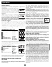
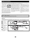
Remote Control Module Connector: allows remote monitoring
and control with an optional module (Tripp Lite model
APSRM4, sold separately). See remote module owner’s manu-
al for connection instructions.
Battery Charge Conserver (Load Sense) Dial: conserves battery
power by setting the low-load level at which the Inverter auto-
matically shuts off. See page 4 for setting instructions.
Multi-Speed Cooling Fan(s): quiet, efficient fans prolong
equipment service life.
Main Ground Lug: properly grounds the Inverter to vehicle
grounding system or earth ground. See page 7 for connection
instructions.
Low Battery Alarm/Shutdown (internal, not shown): auto-
matically detects low voltage and shuts down Inverter to preserve
vehicle battery.
Overload Alarm/Shutdown (internal, not shown): automatically
detects wattage overload on Inverter outlets and shuts down
Inverter as a protective measure.
Ignition Switch Control Jack (rear panel, not shown): use to
connect the Inverter to your vehicle’s ignition switch (with user-
supplied cable) in order to automatically control the Inverter
with the vehicle's ignition switch. See Operation section.
1
2
3
4
5
6
7
8
9
10
Front View (750 & 1250 Models)
13 2
4
5
6
79
10
8