


2 947724
NOTE: Each –24 Vdc screw terminal is fused by a
2 amp WER 2 type fuse. Therefore, when
connecting equipment to this power supply, the load
should be distributed between the (2) 2 amp output
terminals and each load should not exceed 2 amps.
Permanent Installation Instructions
(For use when local codes require conduit to power
supply)
Before beginning this procedure, disconnect power
supply from AC service and customer connections.
1. Open cover of supply. Remove the six (6)
screws holding the faceplate to the cabinet.
2. Using pliers, squeeze the strain relief
bushing associated with the AC input cord.
This enables the removal of the power cord
and strain relief bushing from the unit.
3. Separate faceplate from cabinet. Disconnect
the power cord leads from the supply - black
wire from the circuit breaker; white wire
from the transformer; green wire from the
chassis connection.
4. Using a knockout punch (Greenlee #3807 or
equivalent), enlarge the power cord access
hole to 0.875" diameter to accommodate a
1/2" trade side conduit fitting.
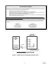
5. Install conduit fitting and run the AC input
leads through the fitting. Connect as
follows:
NOTE: The minimum recommended wire
size for AC input leads is 18 AWG; use wire
rated for at least 105 degrees C.
A. Connect the AC input green/grounding
conductor and the green ground wire from
the faceplate to the chassis connection for
the ground wiring.
B. Connect the black wire to the circuit breaker
terminal using a .250" tab receptacle.*
C. Connect the white wire to the transformer
terminal using a .250" tab receptacle.*
6. Join faceplate to cabinet; replace the six (6)
screws and lockwashers.
7. Reconnect supply to customer connections,
and return power supply to service.
* AMP #42660-2 or an equivalent.
TECHNICAL ASSISTANCE
When trouble is reported, verify the unit is properly
connected and there are no broken connections
leading to this unit.
Assistance in troubleshooting is available from the
factory. When calling, you should have a VOM and a
test set and be calling from the job site. Call (540)
427-3900 and ask for Technical Support, or (540)
427-6000 for Valcom 24-hour Automated Support or
visit our website at http://www.valcom.com.
Valcom equipment is not field repairable. Valcom,
Inc. maintains service facilities in Roanoke, VA.
Should repairs be necessary, attach a tag to the unit
clearly stating company name, address, phone
number, contact person, and the nature of the
problem. Send the unit to:
Valcom, Inc.
Repair and Return Dept.
5614 Hollins Road
Roanoke, VA 24019-5056
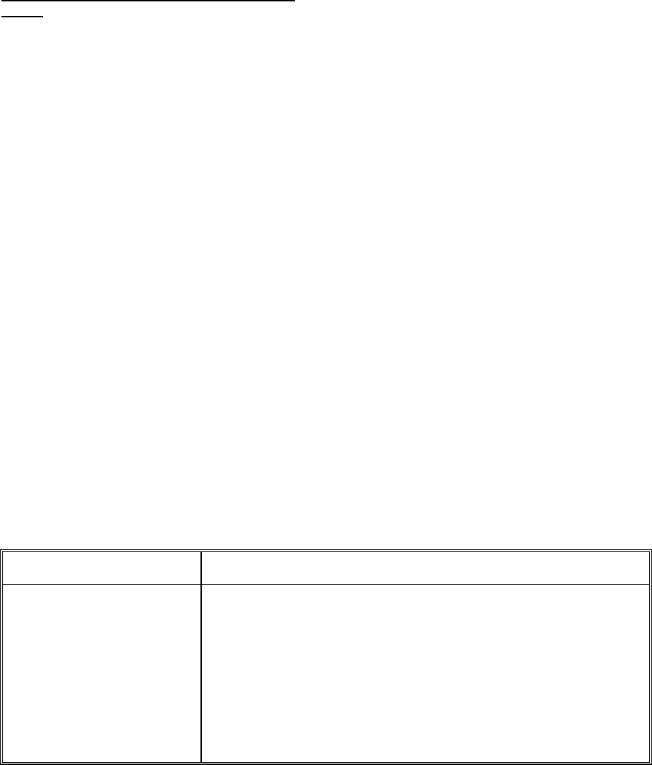
TROUBLESHOOTING CHART
Problem Solution
1. No output.
2. Overload LED lights.
3. Blows fuses.
a. Verify AC present at receptacle.
b. Check for blown fuse.
c. Press circuit breaker to reset.
a. Locate and correct short circuit in output wiring.
b. Verify total equipment power consumption does not exceed 4 amps.
a. Verify total equipment power consumption does not exceed 2 amps per
output.
b. Disconnect AC while making power connections.