


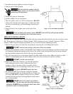
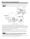
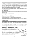

INSTALLATION OF THE WELDING WIRE
The power source is supplied with a spool of .030 MIG Welding Wire. Install the wire into the feeding system
by following the instructions below and referring to Figure 3. MIG (GMAW) welding applications require
argon shielding gas.
Remove the contact tip and gun nozzle from the MIG gun before starting this pro-
cedure.
1. Loosen the nut of the spool holder (brake drum). Remove the spring and the external ring.
2. Remove the plastic protection from the spool. Place it on the spool holder again. Mount the external ring, the
spring and the plastic lock nut again. These parts form the braking system for the wire spool. Tighten nut to
appropriate tightness. Excessive pressure strains the wire feeding motor. Too little pressure does not allow
the immediate stop of the wire spool at the end of the welding.
3. Loosen and lower the plastic knob. Release the upper roll of the feeder. Extract any wire remaining in the
torch liner from an earlier roll of wire.
4. When the wire is disconnected, grasp it with pliers so that it cannot exit from the spool. If necessary,
straighten it before inserting it in the wire input guide. Insert the wire on the lower roll and in the torch
liner.
Keep the torch straight. When feeding a new wire through the liner, make sure
the wire is cut cleanly (no burrs or angles) and that at least 2” from the end is straight (no
curves). Failure to follow these instructions could cause damage to the liner.
5. Lower the upper roll and the knob. Tighten slightly. If tightened too much, the wire gets locked and could
cause motor damage. If not tightened enough, the rolls will not feed the wire.
Figure 3: Wire Installation
10