


REPLACEMENT OF THE WIRE SPOOL
The welding power source is supplied with a mini wire spool of about 0.5 Kg of 0.024” (0.6mm) diameter
wire. When the wire spool is finished it can be replaced with a wire spool of 2 lbs. or 10 lbs.
The wire is pushed by a roll which is moved by a series of mechanisms. The roll has two grooves, one marked by 0.035” (0.9
mm) and the other marked by 0.023” (0.6 mm). It is very important to use the correct groove as explained in “Preparation for
Welding” on page 12. Otherwise, the wire will not feed regularly or it will be crushed. Make sure that the torch tip matches
with the wire diameter. Your welding power source is supplied with a torch, complete with tip, for the wire included with the
power source. For all the other wire spools mount a tip that matches with the wire diameter.
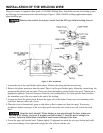
Refer to Figure 3 on page 10. Follow the procedure described in “Installation of the Welding Wire” on page 10
for the replacement of the wire spool.
WELDING TIPS
1. Keep the torch handle with a 45º angle with respect to the workpiece. Maintain the nozzle about 1/4” (0.6
mm) from the surface.
2. Move the torch handle with prudence and steadiness.
3. Avoid welding in areas with too much draft. Too much draft blows away the shielding gas from the weld
pool and mainly causes porosity in the weld.
4. Keep the wire and its cover clean. DO NOT use rusted wire.
5. Avoid sharp bends and kinks on the MIG gun cable.
6. If possible, clean the wire liner with compressed air when replacing the wire spool.
7. Periodically, remove the dust using low pressure air or nitrogen (2-3 bar/30-45 PSI) from the inside of the
power source, to assure adequate heat dissipation from power source during operation.
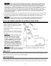
SPOT WELDING
Spot welding is possible by replacing the welding nozzle with a spot welding nozzle. You can buy the spot
welding nozzle from any supplier of Firepower Welding Systems. Spot welding can be performed on carbon
steel sheets of 18 gauge thickness.
Place the spot welding nozzle on the upper sheet. Push firmly on the torch, being sure that the top sheet is in
contact with the bottom one. Press and hold the trigger. Welding will stop automatically after the pre-selected
time. For spot welding, the machine must be set at maximum current and maximum wire speed. We recom-
mend 0.030” welding wire.
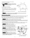
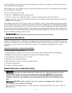
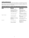
ADJUSTMENT OF THE POWER SOURCE
Set the voltage. Use the correct “stick out.” The wire “stick out” is the dis-
tance between the contact tip and the workpiece. The wire “stick out” (some-
times improperly called the arc length) should remain in the 0.197”-0.394”
(5mm-10mm) range to obtain the best welding (and sound) performance.
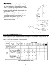
1. Position the voltage switch in the desired position (see Table 1). Select
lower position for lower thickness and higher settings for higher thickness.
2. Adjust the wire speed. Start using a trial metal sheet thoroughly cleaned of
layers of rust or paint. Connect the ground cable to the workpiece. Adjust
the wire speed at the high setting. Press the torch switch.
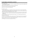
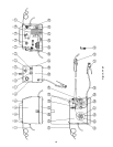
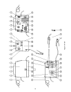
Figure 6: Power Source
14