


ProSpray 3.25 17
GB
Repairs at the unit
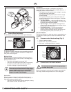
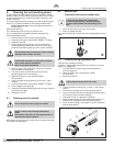
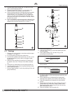
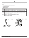
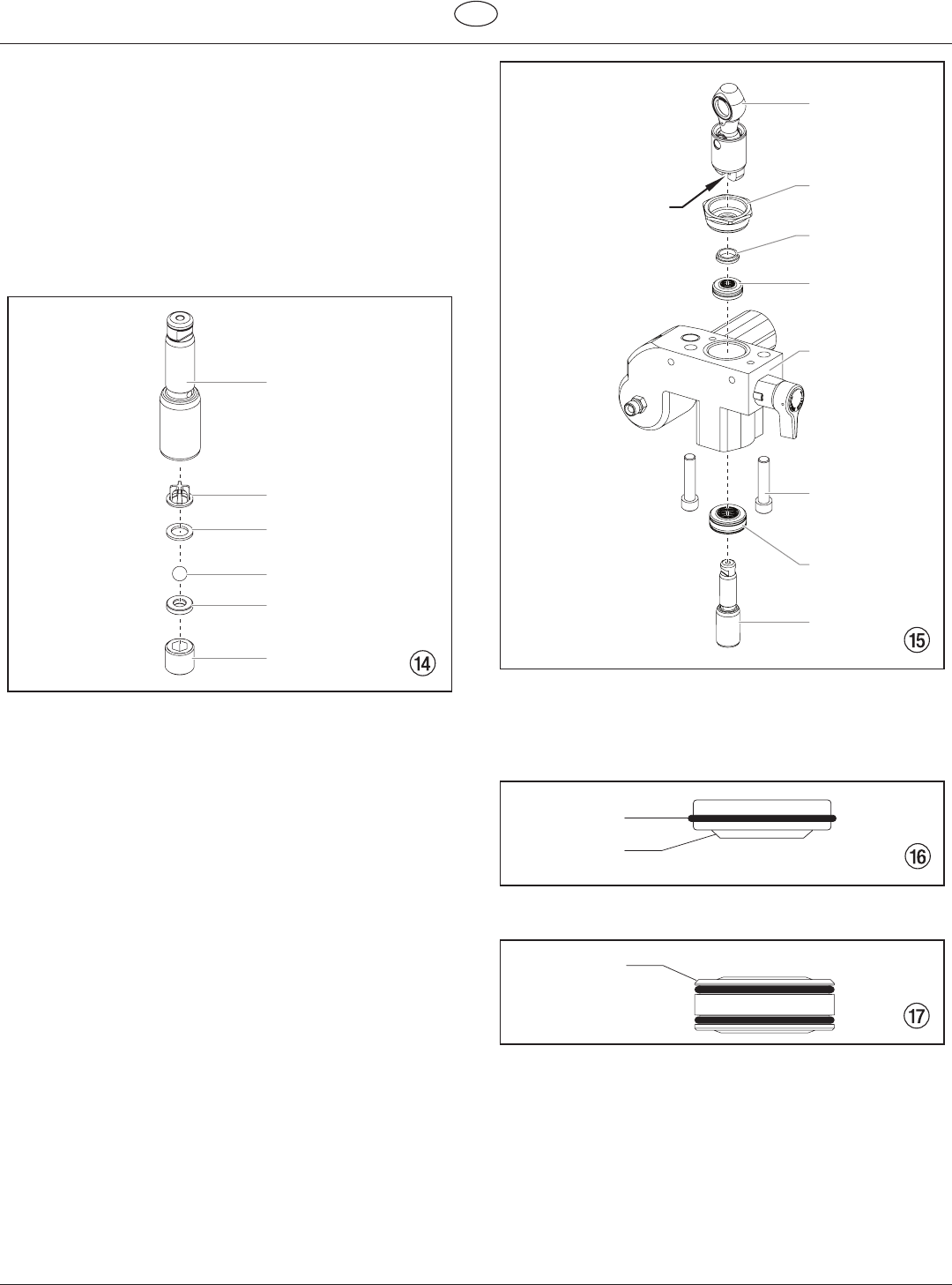
11. Unscrewoutletvalvehousing(Fig.14,Item8)fromthe
piston (9) with adjusting wrench.
12. Remove the upper ball cage (11), crush washer (10),
outlet valve ball (12), and outlet valve seat (13).
13. Clean all the parts with the corresponding cleaning agent.
Check outlet valve housing (8), outlet valve seat (13),
outlet valve ball (12), crush washer (10), and upper ball
cage (11) for wear and replace parts if necessary. If the
worn outlet valve seat (13) is unused on one side, install it
the other way round.
14. Carry out installation in the reverse order. Lubricate O-ring
(Fig. 13, Item 6) with machine grease and ensure proper
seating in the inlet valve housing (Fig. 13, Item 1).
11
10
12
13
9
8
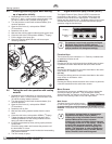
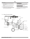
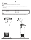
11.3 Packings
1. Remove inlet valve housing in accordance with the steps
in Chapter 11.2, Page 16.
2. It is not necessary to remove the outlet valve.
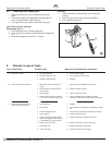
3. Unscrewbothcylinderheadscrews(Fig.15,Item1)from
the pump manifold (2) with a 3/8 inch hexagon socket
head wrench.
4. Slide the pump manifold (2) and piston (3) forward until
the piston is out of the T-slot (9) on the slider assembly
(4).
5. Push piston (3) downward out of the pump manifold (2).
6. Unscrewretainernut(5)fromthepumpmanifold(2)and
remove piston guide (6).
7. Remove upper packing (7) and lower packing (8) from the
pump manifold (2).
4
5
6
7
2
8
1
3
9
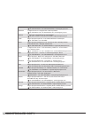
8. Clean pump manifold (2).
9. Lubricate upper packing (7) and lower packing (8) with
machine grease.
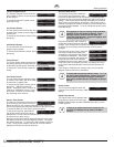
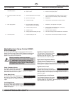
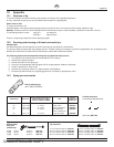
10. Insert upper packing (Fig. 16) with O-ring (1) and
protruding lip (2) downward.
1
2
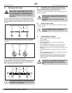
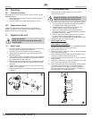
11. Insert lower packing (Fig. 17) with the beveled edge (1)
facing upward.
1
12. Insert piston guide (Fig. 15, Item 6) into the retainer nut
(5). Screw retainer nut (5) into the pump manifold (2) and
tighten by hand.
13. Push installation tool (included with the replacement
packings) for the piston (3) from above onto the piston.
14. Lubricate installation tool and piston (3) with machine
grease.
15. Guide piston (3) through the lower packings (8) into the
pumpmanifold(2)frombelow.Usingarubbermallet,
lightly tap the piston (3) from below until it can be seen
above the pump manifold.
16. Remove installation tool from piston (3).
Uncontrolled Copy