


2
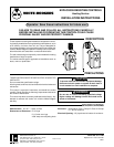
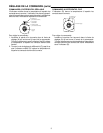
INSTALLATION OF REMOTE BULB TYPES
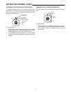
On controls with internal adjustment, the electric power must be
disconnected before removing the front cover to change the dial
setting. This prevents the possibility of an explosion from arcing
at the control contacts while cover is off.
On controls with external knob adjustment, the external knob
points to the cut-out temperature.
When replacing the cover on controls with an external knob, set
the internal dial and the external dial to the same setting so that
hole in dial lines up with pin on the arm that is operated by the
knob.
SETTING THE CONTROL
9
0
8
0
7
0
6
0
5
0
4
0
1
0
1
5
2
0
2
5
3
0
5
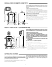
3-11/16"
1-1/16"
4"
6-1/8"
1-1/16"
4-5/8"
4 HOLES
5/16" DIA.
4-5/8"
2-5/8"
1/2"-14
NPT
THREAD
1-15/16"
5/8"
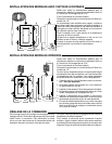
INSTALLATION OF SELF-CONTAINED TYPES
After a suitable location has been chosen for the control, remove
the front cover by using a 3/16" Allen head wrench in the 6 cover
screws.
Fasten control to mounting surface.
Use 1/2" pipe for connection to electrical outlet.
The proper location of the self-contained thermostat is very
important as it depends on average air temperature for proper
functioning. The following general rules will help in determining
the proper location.
1. Make sure that it is in a place where air circulates freely. This
is important.
2. Never install it on or near an outside wall.
3. Keep it away from windows and doors.
4. Don’t locate it too close to cold water pipes, evaporators,
coils, etc.
5. Mount it on a post or partitioning wall, but make sure there
are no pipes or coils in that wall or directly behind it.
6. If the conduit goes to a warmer room, put rock wool around
the wires in the pipe where it enters the control to keep warm
humid air out of the switch.
1-1/16"
4"
6-1/8"
1-1/16"
4 HOLES
5/16" DIA.
4-5/8"
3-11/16"
2-5/8"
4"
1/2"-14
NPT THREAD
After a suitable location has been chosen for the control, remove
the front cover by using a 3/16" Allen head wrench in the 6 cover
screws.
Fasten control to mounting surface.
Use 1/2" pipe for connection to electrical outlet.
The switch mechanism of remote bulb types may be mounted at
any convenient point away from the controlled area within the
length of the capillary. The least possible amount of capillary
should be put into the controlled area.
The bulb should be located so as to be in the average tempera-
ture of the area to be controlled.
The bulb should not be attached to any surface but should be
held away from the mounting surface by brackets.
Excessive capillary should be coiled and secured in some
convenient location close to the switch mechanism.
1-11/16"
1-15/16"