


8
Features
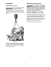
Miter Cutting Head
The miter cutting head is the unit that cuts the
material and consists of a cast iron base, blade
support unit and guard, transmission unit, and
motor. The depth of cut is set by adjusting the
depth cut stop. The miter cutting head swivels
and locks into -45º, 90º, and +45º by means of a
locking mechanism. Depressing the mechanism
overrides the lock, permitting the head to adjust
to any position between -45º and +45q.
Miter Position Lock
The miter position lock secures the miter cutting
head from movement. The miter is secured
when the lock is pushed all the way to the left
and can be positioned when the lock is moved to
the right.
Self-centering Vise
The self-centering vise holds the work piece in
place during cutting. The work piece is secured
in the vise by turning the vise handles.
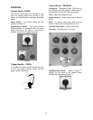
FK350 Controls
The control panel consists of the Power (On/Off)
switch and High/Stop/Low switch, and an
integral coolant system. To operate the
machine, the Power switch must be set to on
and the High/Stop/Low switch must be set for Hi
or Low. Then depress the trigger handle to start.
FK350-SX Controls
This machine features a 2-speed motor, feed
speed control, an integral coolant system, and
two modes of operation; manual mode, and
semi-automatic mode. In semi-auto, the
complete cut cycle is initiated via push button.
The semi-auto cut cycle closes the vise
clamping the material, powers the head down
completing the cut, then raises the head, and
opens the vise. In manual mode, head up/down,
and vise open/close is initiated by switches.
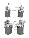
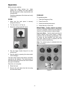
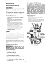
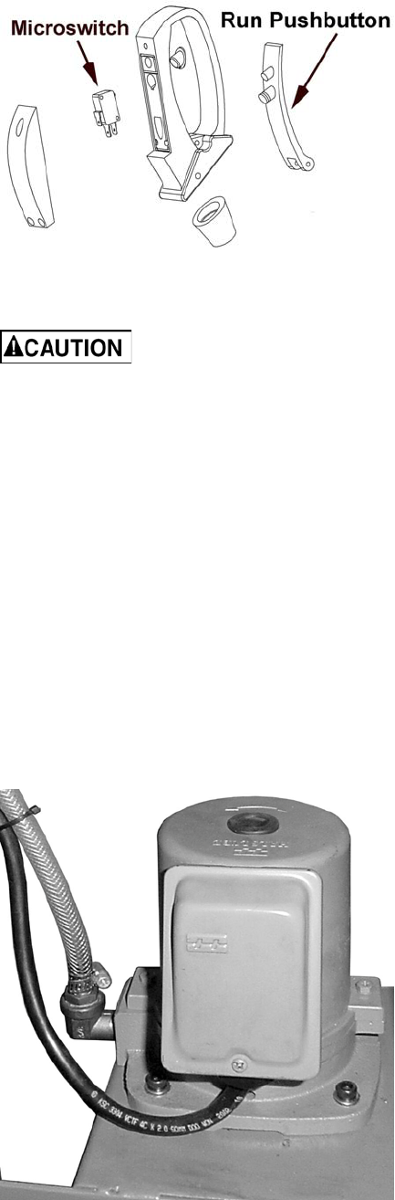
Trigger Handle
The trigger handle (Figure 1) is located on the
operating lever used to raise and lower the saw.
It contains a micro-switch, which is activated
when the operator depresses the run trigger.
Figure 1
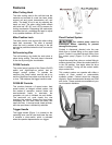
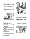
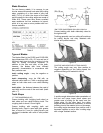
Flood Coolant System
The coolant pump must be
submerged before operating to prevent
damage to the pump.
Coolant is dispensed directed onto the saw
blade from a coolant fitting on the upper blade
guard. Coolant is provided through tubing from
the coolant pump (Figure 2) in the machine
base.
Adjust the coolant flow valve on coolant fitting to
achieve desired flow. When the coolant switch is
in the ON position, flow starts when the drive
motor is started. Turning off the coolant switch
stops coolant flow.
This coolant system can operate with either a
soluble oil base coolant or water-soluble
synthetic coolant. Coolant should be changed
regularly. Some recommended brands are DoAll
and Lenox. These coolants are available at your
local industrial distributor.
Figure 2