Page 5SKU 94331
Note: The table may need to be cut and routed to
accept this insert.
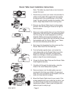
Decide how you want your router to be oriented in
relation to the table. We suggest that the handles
be aligned with the long dimension of the Table
Insert. You also should consider the location of the
switch, height adjustment knob & locking lever.
Be sure your Router Table Insert is in the proper
position, with the starting pin holes to the right of
the bit location.
Place your router upside down on top of the Router
Table Insert, with the router in the desired position.
You’ll be using the router baseplate as a drilling
template. Before removing the baseplate, put a
mark or piece of tape at the front and center of both
the baseplate and the Router Table Insert. These
will serve as reference points later on.
Next rmove the baseplate from the router and the
Router Table Insert from the table top.
Turn both plates upside down, and center the
router base plate on the Router Table Insert (the
concentric rings will help with this alignment).
Make sure the tape or marks you placed on the
plates in step #3 are oriented properly.
Clamp the Router Base Plate and the Router Table
Insert together securely.
Carefully drill through the table plate, using the
holes in the router base plate as guides.
Remove clamps, turn the table plate over and
countersink the holes you drilled in the previous
step. Run your countersink at slow speed, and use
care not to countersink too deep.
Mount the Router Table Insert to your router. If the
screws supplied with your router are too short, you
can obtain longer screws from hardware or auto-
motive parts stores. Lower router and plate into
table and you’re ready to go!
Router Table Insert Installation Instructions
1.
2.
3.
4.
5.
6.
7.
8.
9.


