


©2000 Xantrex Technology Inc.
Menu Maps
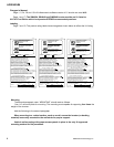
The USER and SETUP menu have been updated to reflect the new software revision as follows:
Page 34USER MENU. The software revision shown under menu heading TRACE
ENGINEERING 3, menu item REVISION 4.01 is changed to REVISION 4.10.
An information file has been added to menu heading 11 and reads: IN SELL MODE AC1
INPUT VAC LIMITS FIXED AT 88% AND 110% OF NOMINAL.
Menu System
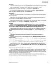
Page 39TRACE ENGINEERING (3) menu heading. The software revision has been updated
from 4.01 to 4.10.
Page 48The SET MAX CHARGE AMPS AC menu item, the range has been changed from
01 to 35 amps to 01 to 40 amps for the SW5548 model.
Page 54BATTERY SELLING (17) menu heading. The SET MAX SELL AMPS AC range has
been changed from 01 to 35 amps to 01 to 50 amps for SW5548 model.
Operation
Page 61 The following paragraph should be added to the UTILITY INTER-ACTIVE MODE
bulleted item: To meet agency approvals, SELL mode will sell power only between the locked
106132 volts AC range and 59.360.5 Hz range windows (120 VAC/60 Hz models only).
Page 83When in SELL mode, the SET INPUT LOWER LIMIT VAC is locked at 106 VAC and
sells power only when the AC output of the inverter is between 88 to 110% of nominal AC line
voltage.
Display Deletions
The following menu display items have been deleted for various reasons unrelated to UL
requirements.
Under the ERROR CAUSES 5 menu heading, menu item INVERTER BREAKER TRIPPED
has been deleted.
Under the GENERATOR MODE 2 menu heading, menu item GEN MAX RUN TIME ERROR
has been deleted.
Under the GENERATOR MODE 2 menu heading, all references to the GEN MAX RUN TIMER
have been deleted (i.e., IF GEN RUNS FOR MORE THAN MAX RUN TIME THEN ERROR).
Under GEN AUTO START SETUP 12 menu heading, all references to the GEN MAX RUN
TIMER have been deleted (i.e., SET MAXIMUM RUN TIME H:M 08:00 and SET MAX RUN TIME
TO 0 TO DEFEAT).
Utility Interactive Mode Islanding Protection Compliance
Trace SW inverters are capable of utility interactive operation, which includes utility protection
features to prevent injury and damage from occurring when power is sold to the utility grid. These
protective systems utilize high-speed microprocessor hardware and software to detect the abnormal
conditions and disconnect the inverter from the utility grid.
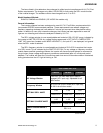
The UL1741 standard requires specific responses by the inverter to abnormal voltage and
frequency conditions. The following summarizes the voltage and frequency levels and the response
time period required, plus other features required by the UL1741 standard.
3
ADDENDUM