GB - 11
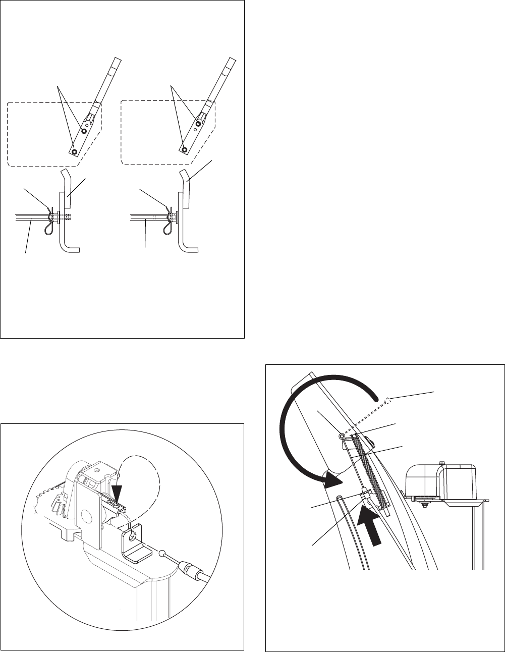
6. Insert the chute lock cable fitting into the bracket
on the chute pedestal, and then connect the
chute lock cable to the lock teeth by fitting the
cable ball end into the slot on the lock teeth.
NOTE: Press down on lock teeth with your finger to
align the cable ball end with the slot.
7. Replace the gear cover removed in step 1.
IMPORTANT: Rotate the discharge chute to the left
when tightening the pedestal hardware to ensure
clearance between the discharge chute and the belt
cover.
8. Tighten pedestal hardware to 15–31 lbf-ft
(20-42 N•m).
9. Make sure the discharge chute rotates left and
right when you push the discharge chute control
lever left and right.
Deflector Remote
NOTE: Connect the cable end to the cable anchor on
the discharge deflector before clipping the cable to the
cable bracket on the discharge chute.
1. Route deflector remote cable along the left side of
the chute pedestal.
2. Insert the barrel on the cable end into the bracket
on left side of chute deflector (Figure 9).
3. Hold seal out of the way while routing the cable
through the bracket on the left side of the
discharge chute, and then push the cable fitting
into the bracket.
4. Push the seal securely over the end of the cable
fitting to prevent water from entering the cable.
5. Check deflector travel. Adjust nut on cable end
under handlebar to obtain full travel, if necessary.
(See Deflector Remote on page 24.)
Figure 7
1.Chute Control Assembly
2.Hair Pin
3.Chute Rod
4.Handlebar Mounting Hardware
2
1
1
2
3
3
Use the handlebar hardware locations on the side
of the unit frame to determine which hole gets used
to secure the chute rod to the control assembly.
OS7156
4
4
Figure 8
OS7270
Figure 9
1.Cable Anchor
2.Cable End
3.Deflector Cable
4.Cable Fitting
5.Cable Bracket
1
2
3
5
4
3
OS7070
