Receiving & Installation 3–7MN735
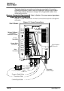
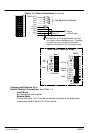
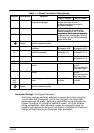
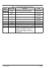
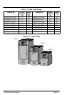
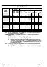
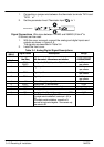
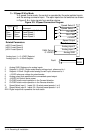
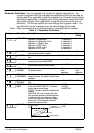
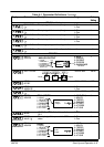
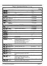
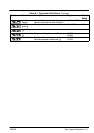
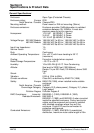
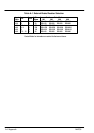
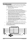
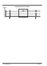
Table 3-3 Power Connection Descriptions
Range
Terminal Description Function
230V 1–Phase 460V 3–Phase
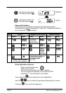
RLY1 Relay Output Normally open, programmable
contact for a relay output.
Contact closes when the programmed
condition (see Section 4) is true.
No voltage is present on this contact. 6
conditions are available.
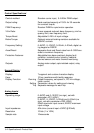
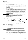
TH1A Thermistor Connection to motor thermistor It is good practice to protect motors by using
thermistors. A typical resistance (up to a
reference temperature of 125_C) is 200Ω,
rising rapidly to 2000Ω above this temperature
TH1B Thermistor Connection to motor thermistor
r
s
ng rap
y
o
a
ove
s
empera
ure.
Connect devices in series between TH1A and
TH1B. Jumper TH1A and TH1B if temperature
sensors are not used.
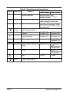
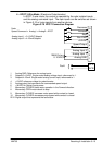
Reference
Terminal
Supply protective earth (PE). This terminal must be connected to a protective (earth)
ground for permanent ground.
L1 Power Input Single and three phase line
connection
220/240VAC±10%
with respect to L2/N.
380/460VAC±10%
with respect to L2, L3.
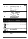
L2/N
L2
Power Input Single phase neutral (or L2 three
phase line connection)
220/240VAC±10%
with respect to L1.
380/460VAC±10%
with respect to L1, L3.
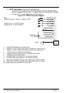
L3 Power Input Three phase line connection Not applicable 380/460VAC±10%
with respect to L1, L2.
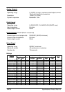
DC- No user connection
DC+ Dynamic Brake Connection to external brake
resistor
Not applicable Frame 2 (high volt
only) & 3.
See Internal Dynamic
Brake Switch" table
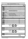
DBR Dynamic Brake Connection to external brake
resistor
Not applicable Frame 2 (high volt
only) & 3.
See Internal Dynamic
Brake Switch" table
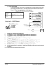
M1/U
M2/V
M3/W
Power Outputs 3-phase supply connection for
motor
0 to 220/240VAC
0 to 240Hz
0 to 380/460VAC
0 to 240Hz
Reference
Terminal
Supply protective earth (PE). This terminal must be connected to a protective (earth)
ground for permanent ground.