-9-
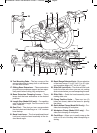
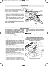
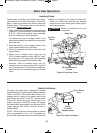
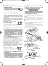
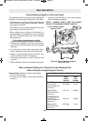
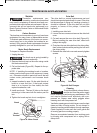
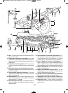
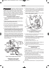
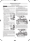
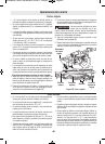
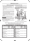
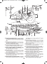
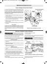
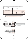
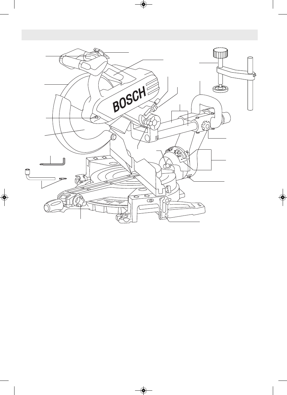
"D;C8%DA?>B4)>>;">34;>=;H – Used
for loosening/tightening the blade and for fence
adjustments.
"D;C8%DA?>B4O!P,A4=27<<">34;
>=;H – Used for loosening/tightening the
blade.
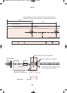
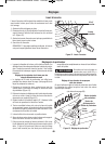
4E4;4C4=C%8=A>F=">;38=6(4CC8=6 –
Allows you to easily lock the head assembly to
the bevel angle of 33.9° to the left or right.
4E4;(20;4 – This scale is large and angled to
allow you to easily read bevel angles.
403 BB4<1;H !>2: %8= – The saw is
equipped with a lock pin used to lock the head
assembly in the lower position for transporting.
&D82:'4;40B44?C7(C>?DCC>= – Allows
you to quickly release the depth stop.
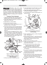
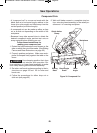
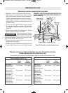
4?C7(C>? 8=439DBC<4=C =>1–Allows
you to adjust the depth of the blade for cutting
grooves in the workpiece (Figure 13, page 16).
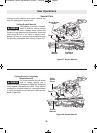
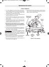
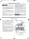
0=3;4'>C0C8>='4;40B4!4E4A">34;
>=;H – Pulling this lever allows the handle to be
rotated. Release the lever into one of four oper-
ating positions.
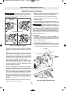
'40A0AAH8=60=3;4MUsed for lifting of the
tool.
0=3;4;0<?">34;>=;H MLocks han-
dle in the selected position.
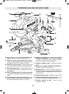
A1>A!>2:—Allows the user to keep the blade
from rotating while tightening or loosening arbor
screw during blade replacement or removal.
A>=C0AAH8=60=3;4 – Used for lifting the
tool.
!>F4A D0A3 2CD0C8>= !8=: – Allows for
smooth movement of the lower guard.
*??4A;034D0A3 – Covers upper portion of
the blade.
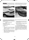
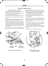
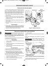
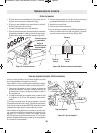
4CC8=6)> =>F.>DA"8C4A(0F