2-16 RAID Array 3000 Pedestal Storage Subsystem Hardware User’s Guide
Compaq Confidential – Need to Know Required
Writer: Bob Young Project: RAID Array 3000 Pedestal Storage Subsystem Hardware User’s Guide Comments:
Part Number: EK-SMCPO-UG. C01 File Name: c-ch2 RAID Array Controller.doc Last Saved On: 12/4/00 1:51 PM
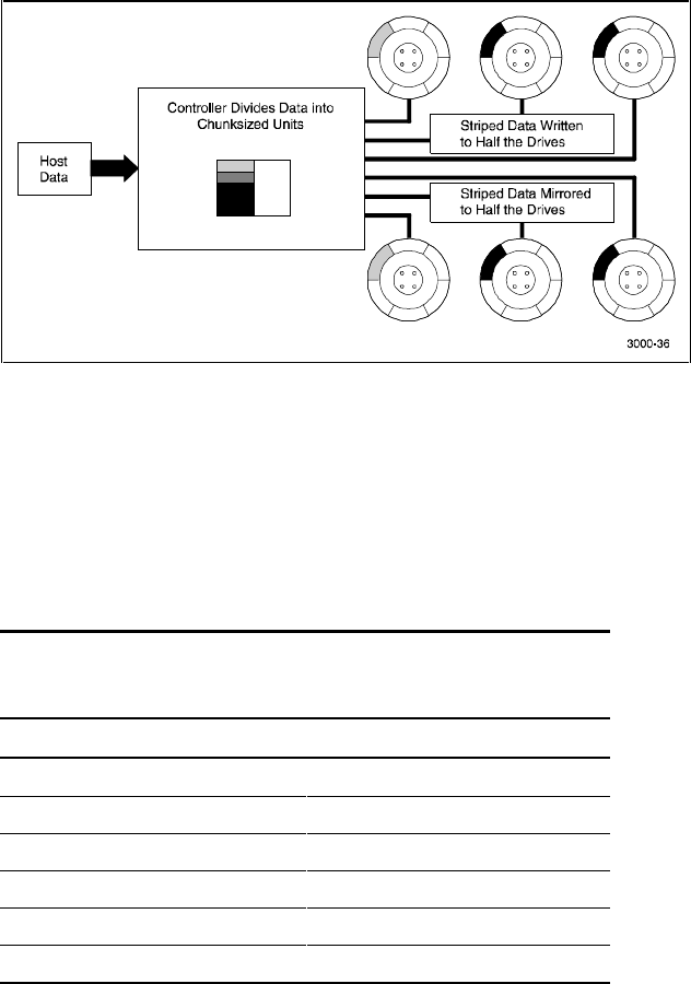
Figure 2-6 shows a diagram of RAID 0+1 write.
Figure 2-6. Diagram of RAID 0+1 write
In the event of a drive failure, a RAID 0+1 array will enter degraded mode and
continue to operate by substituting the failed drive with its mirror.
When the controller creates a RAID 0+1 set, it first sorts the drives by channel
number and SCSI ID. Then it stripes the data across every other drive and
forms a mirrored pair with the first two drives, another mirrored pair with the
second two drives, and so on. Table 2–5 lists how the controller uses the drives
in a RAID 0+1 set.
Table 2-5
RAID 0+1 Example
Drives Selected Function
Channel 1, ID 0 First member of stripe set
Channel 1, ID 1 Mirror of channel 1, ID 0
Channel 1, ID 2 Second member of stripe set
Channel 2, ID 0 Mirror of channel 1, ID 2
Channel 2, ID 1 Third member of stripe set
Channel 2, ID 2 Mirror of channel 2, ID 1