UPS Electrical Installation
8
Bottom Cable Entry
When making the power connections for bottom cable entry, the recommended order of pull-
ing and installing cables is to start from the bottom connections to the top connections. The
cables must be routed around the fault braces (see Detail in Figure 9). This is to prevent the
cables from contacting other busbars. The recommended conduit layout is shown in Figure 7.
5. For control connection details, see 2.3 - Control Cable and Communications.
6. Close and secure the interior and exterior doors.
2.3 Control Cable and Communications
Based on your site’s specific needs, the UPS may require auxiliary connections to manage the battery
system (external battery circuit breaker), communicate with a personal computer or provide alarm
signaling to external devices or for Remote Emergency Power Off (REPO). The External Interface
Board, arranged for this purpose, is on the rear of the operator access door.
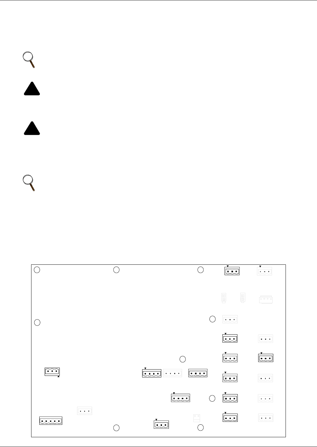
Figure 2 External Interface Board connections layout
NOTE
For a Single Input configuration, linking busbars must be installed between the bypass and
the rectifier input.
!
WARNING
Risk of electrical shock. Can cause injury or death.
If the load equipment will not be ready to accept power on the arrival of the commissioning
engineer, ensure that the system output cables are safely isolated at their termination.
!
WARNING
Risk of electrical shock. Can cause injury or death.
When connecting the cables between the battery extremities to the circuit breaker always
connect the circuit breaker end of the cable first.
NOTE
If fault bracing brackets were removed during installation, they MUST be replaced.
EPO
STATUS
TB0823
BATT
MTR OPT
LBS
VOLTAGE
TB0826
REPO
FORM C
TB0824
LEPO
KEY
STATUS
TB0825
EXTERNAL
CAN
TB0829
INT BATT
CAN
EXT BATT
CAN
TB0820
INV
CNTRL
RECT
CNTRL
BIB
MBB
BYP
CNTRL
ON GEN
RIB IN
TB0812
TB0813
TB0816
TB0810
ACT FILT
STATUS
MIB
MOB
TB0811
TEMP 1 TEMP 2
BATT GND FLT
MAINT BYP
ENABLE
ACT FILT
CNTL
TB0821
REPO


