Installation Instructions (cont'd)
AWARNING
• The applianceandits individualshutoffvalvemustbe discon.
nected from the gassupplypipingsystemduringanypressure
testing of the gas system at test pressuresin excessof '/2
poundpersquareinch(3.5kPa).
• The appliancemustbe isolatedfrom the gassupplypipingsys-
tem byclosingits individualmanual shutoff valve duringany
pressuretesting of the gassupplypiping systemat test pres-
soresequalor lessthan _ poundper squareinch(3.5kPa).
J AWARNING -1
Use pipe joint compound or teflon tape marked as being[
resistantto the acldonofpoUoleum [Propane(LR)] gase_ [
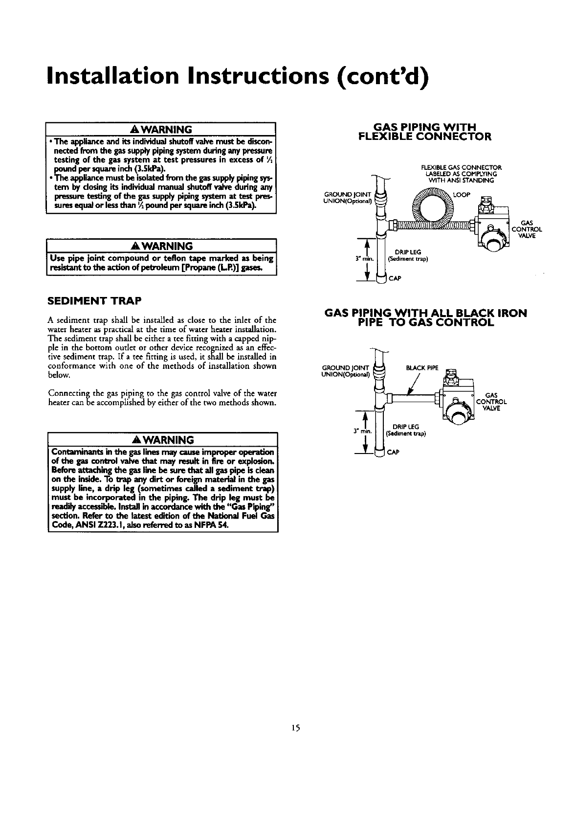
SEDIMENT TRAP
A sediment trap shall be installed as close to the inlet of the
waterheater as practical at the time of waterheater installation.
The sediment trap shall beeither a tee fitting with a capped nip-
ple in the bottom outlet or otherdevice recognizedas an effec-
tivesediment trap. If a tee fitting is used, it shall be installedin
conformance with one of the methods of installation shown
below.
Connectin_ the gaspiping to the gas control valveof the water
heater canoe accomplishedby either of the twomethods shown.
&WARNING
Contaminants in the gaslinesmay causeimproper operation
of the gascontrol valve that may result in fire or explosion.
Beforeattaching the gasline be sore that ell gaspipe isclean
on the inside.To trap any dirt or foreignmateriel in the gas
supply line, a drip leg (sometimes called a sediment trap)
must be incorporated in the piping. The drip leg must be
readilyaccessible.Installin accordance with the "Gas Piping"
section. Refer to the latest edition of the National Fuel Gas
Code, ANSI 7.223.1,also referred to as NFPA 54.
GAS PIPING WITH
FLEXIBLE CONNECTOR
GKOUND
UNION(OlXional)
FLEXIBLE GAS CONNECTOR
LABELED AS COt'IPLYING
WITH ANSI STANDING
DRIPLEG
(Sedimenttrap)
ICAP
GAS PIPING WITH ALL BLACK IRON
PIPE TO GAS CONTROL
GROUND JOINT BLACK PIPE
UNION(Optional)
GAS
CONTROL
VALVE
GAS
CONTROL
VALVE
15
