Installation Instructions (cont'd)
Venting (cont'd)
CONNECTING PVC PIPE VENT TO BLOWER
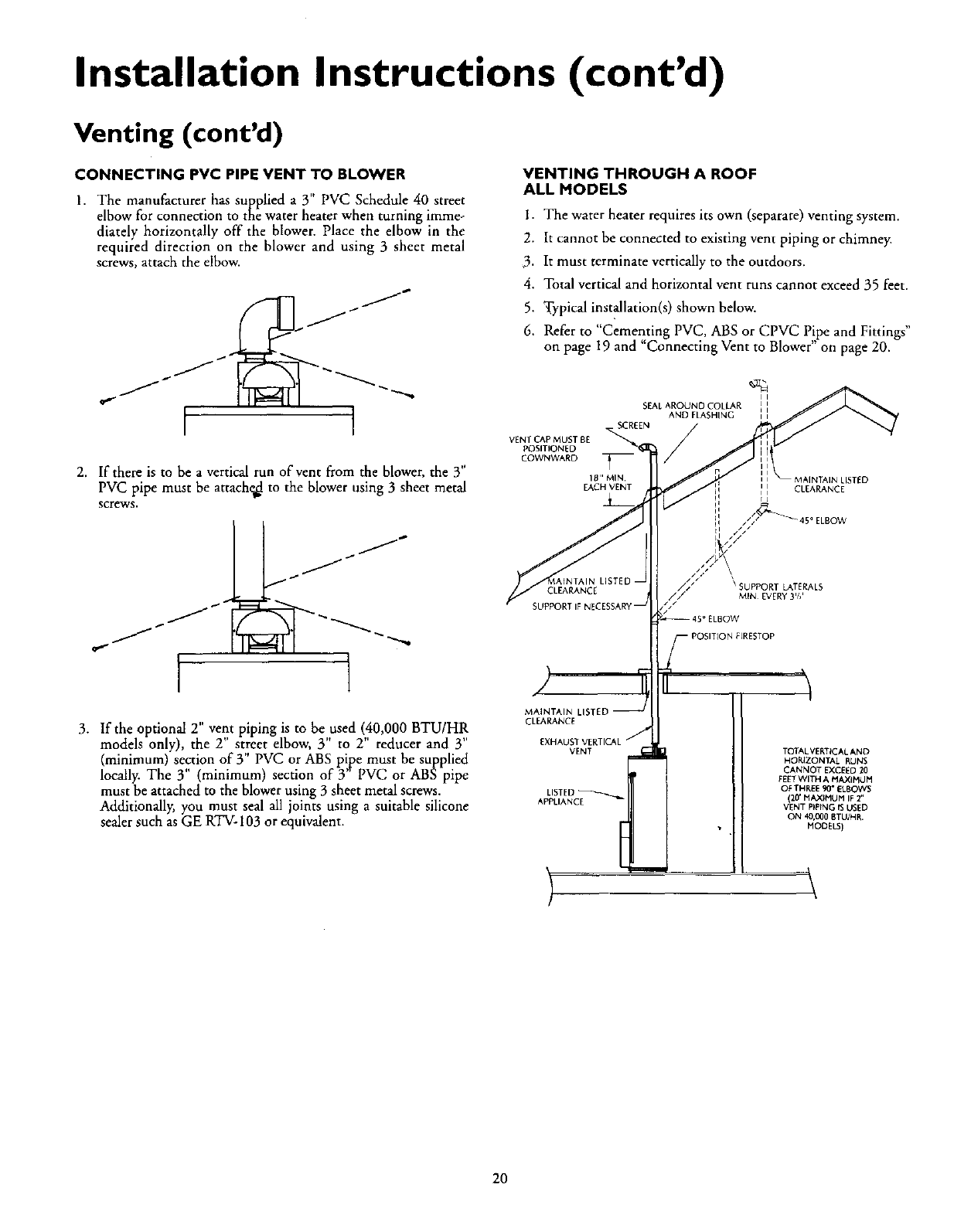
I. The manufacturer has supplied a 3" PVC Schedule 40 street
elbow for connection to the water heater when turning immeo
diately horizontally off the blower. Place the elbow in the
required direction on the blower and using 3 sheet metal
screws, attach the elbow.
(AJ
,a -/ [L[_T_ "- _"-_
I I
2. If there is to be a vertical run of vent from the blower, the 3"
PVC pipe must be attache_ to the blower using 3 sheet metal
screws.
I 1
3. If the optional 2" vent piping is to be used (40,000 BTU/HR
models only), the 2" street elbow, 3" to 2" reducer and 3"
(minimum) section of 3" PVC or ABS pipe must be supplied
locally. The 3" (minimum) section of 3"PVC or ABS pipe
must be attached to the blower using 3 sheet metal screws.
Additionally, you must seal all joints using a suitable silicone
sealer such as GE RTV- 103 or equivalent.
VENTING THROUGH A ROOF
ALL MODELS
I. The water heater requires its own (separate) venting system.
2. It cannot be connected to existing vent piping or chimney.
3. It must terminate vertically to the outdoors.
4. Total vertical and horizontal vent runs cannot exceed 35 feet.
5. Typical instMlation(s) shown below.
6. Refer to "Cementing PVC, ABS or CPVC Pipe and Fittings"
on page 19 and "Connecting Vent to Blower" on page 20.
VENTCAP MUST BE
POSITIONED
COWNWARD
SEAL AROUND COLLAR
AND FLASHING
. SCREEN /
18" MIN
EACH VENT
CLEARANCE
SUPPORTIFb
MAINTAIN
CLEARANCE
VENT
APPLIANCE
MAINTAIN LISTED
CLEARANCE
/.//_ S_/ \_\SUPPORTMINEVERY3'_'LATERALS
TOTAL VERTICAL AND
HORIZONTAL RUNS
CANNOT EXCEED 20
FEETWITH A MAXIHiAH
OF TI4REE90" ELBOWS
(20' HAX_t4UM IF2"
VENT P_PrNG tS USED
ON 40,000 BTU/NR.
MODELS)
\
20
