Installation Instructions (cont'd)
AWARNING
• Theq3pliancerand_ individualshutoffvalsemasthediscon-
nectedfromthelas _3ply pipingI_-m duringmr¢prassure
testingof the gassystemat test pressuresin excessof
. peundpersc_relech(3.SkP',).
Theapprmsemustbeiselatedfromthe_s supplypipinlsys-
ternbydosingitsindividualmanualshutoffvalveduringany
pressuretastingofthe gassupplypipingsystemat testpras-
suresequalorless_ _ poundpersquareinch(3.5kPa),
I &WARNING
Use pipejoint compoundor teflon tapemarkedasbeingJ
GROUND
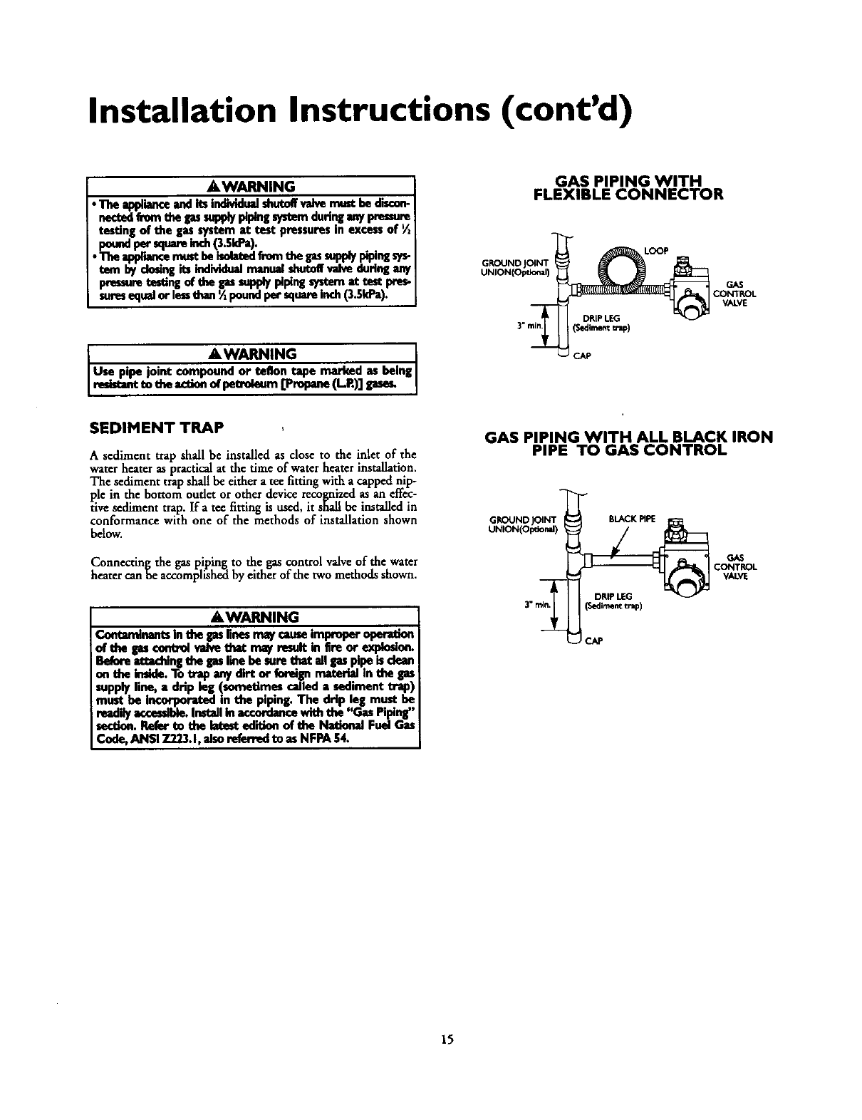
GAS PIPING WITH
FLEXIBLE CONNECTOR
LOOP
CAP
GAS
CONTROL
VALVE
SEDIMENT TRAP
A sediment trap shall be installed as close to the inlet of the
waterheater as practicalat the time ofwaterheater installation.
The sediment trap shallbe eithera tee fittingwith a capped nip-
ple in the bottom oudet or otherdevicerecognized asan effec-
fivesediment trap. Ira tee fitting is used, it shall be installed in
conformance with one of the methods of installation shown
below.
Connecting the gas piping to the gascontrol valveof the water
heater canhe accomplishedby either ofthe two methods shown.
AWARNING
ContaminentsInthe Ipsrmesn_/came i_ oper_on
of the gas€ontrolvalvethat r,_/rasult intireor expleslen.
Be(oreIttKhleg thegasIleehesurethat angaspipeisdean
onthe imlde.To_ap any dirtor foreignmateslalInthe gas
supplyline, a drip leg (sometimes called a sediment trap)
must be incocperated in the piping. The drip leg must he
readilyaccessible.Installinaccordancewith the "Gas Piping,"
sectine.Refer to the letest ediUon of the National Fuel Gas
Code, ANSI 7.223.1,alse re_-md to as NFPA 54.
GAS PIPING WITH ALL BLACK IRON
PIPE TO GAS CONTROL
LJCAP
15
