THEORY OF OPERATION
E-3 E-3
VANTAGE® 500
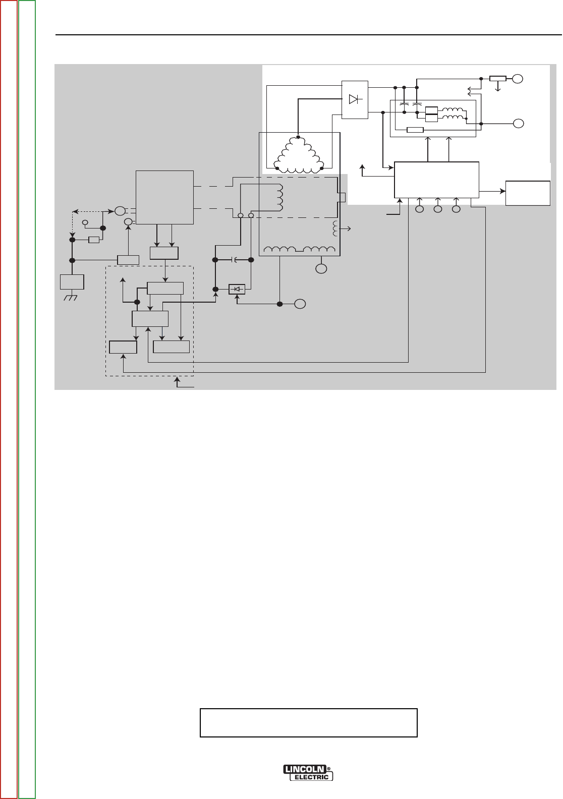
FIGURE E.3 - WELD WINDINGS, RECTIFIER, POWER MODULES AND FEEDBACK
WELD WINDINGS, RECTIFIER,
POWER MODULES AND
FEEDBACK
The three-phase stator weld windings are connected to a
three-phase rectifier bridge. The resultant DC voltage is
applied to four paralleled capacitors incorporated within each
of the two power modules. There are two capacitors in each
module. These capacitors function as filters and also as
power supplies for the IGBTs. See IGBT Operation in this
section. The IGBTs act as high-speed switches operating at
20KHZ. These devices are switched on and off by the Weld
Control PC board through pulse width modulation circuitry.
See Pulse Width Modulation discussion in this section.
This chopped" DC output is applied through choke coils and
a shunt to the welding output terminals. The choke functions
as a current filter, and it helps to balance the outputs of the
two power modules. Free-wheeling diodes are incorporated
in the power modules to provide a current path for the stored
energy in the choke when the IGBTs are turned off. See the
Chopper Technology discussion in this section.
Output voltage feedback from the output terminals and current
feedback from the shunt is fed to the Weld Control PC board
as a means of controlling the output.
NOTE: Unshaded areas of Block Logic
Diagram are the subject of discussion
ENGINE ROTOR
STATOR
AUXILIARY WINDINGS
W
E
L
D
W
I
N
D
I
G
MECHANICAL
ROTATION
ALTERNATOR
OUTPUT
CONTROL
MODE
SELECT
SWITCH
SLIP
RINGS
ARC
CONTROL
WELD
CONTROL
BOARD
VOLTMETER
AMMETER
42 VAC and 120VAC
to 14 Pin Amphenol
for Wire Feeder
(No 120 VAC on EURO Models)
THREE-PHASE
RECTIFIER
++
++
____
TO WELD
CONTROL
BOARD
__
START
BUTTON
+
BATTERY
ON
STARTER
+12 VDC
RUN
ENGINE
SENSORS
OIL
PRESSURE
WATER
TEMP.
PERIPHERAL
PCB
PULL
COIL
PCB
+12 VDC
RUN
FUEL
SOLENOID
PULL
HOLD
FLASHING
IDLER
SOLENOID
LOW IDLER SIGNAL (TO SUPPLY PULL VOLTS)
HOLD VOLTS FROM CONTROL PCB
25•
(COLD)
120 VAC
RECEPTACLES
(Not on EURO Machnes)
AC RECEPTACLES
Various combinations of
1Ø and 3Ø Outputs.
See Techincal Specs.
IGBT
IGBT
CHOKE
R4-50•
2-POWER MODULES
SHUNT
TO
CONTROL
PCB
AUX. POWER
USE SENSING
+12VDC
RUN
80 VDC
PWM
SIGNAL
PWM
SIGNAL
120VAC
160VDC
120VAC
PULL
RUN/STOP
SWITCH
* On some codes the Peripheral Board, Pull Coil Board, Idler Solenoid & Fuel Solenoid are
replaced by an Electronic Governor Control module and components. See Wiring Diagram.
Return to Section TOC Return to Section TOC Return to Section TOC Return to Section TOC
Return to Master TOC Return to Master TOC Return to Master TOC Return to Master TOC


