Commander GP User Guide
Issue code: gpxu2
Setting Up the Drive 3-49
Setting up and using Macro 7
The following may require attention in addition to
the settings made in Chapter 2.
Frequency control
When Macro 7 is selected, the Drive always operates
in brake control; unlike Macros 2 to 5, no digital
input exists to allow switching to and from normal
frequency control.
The frequency of the motor is controlled in the
same way as in normal frequency control.
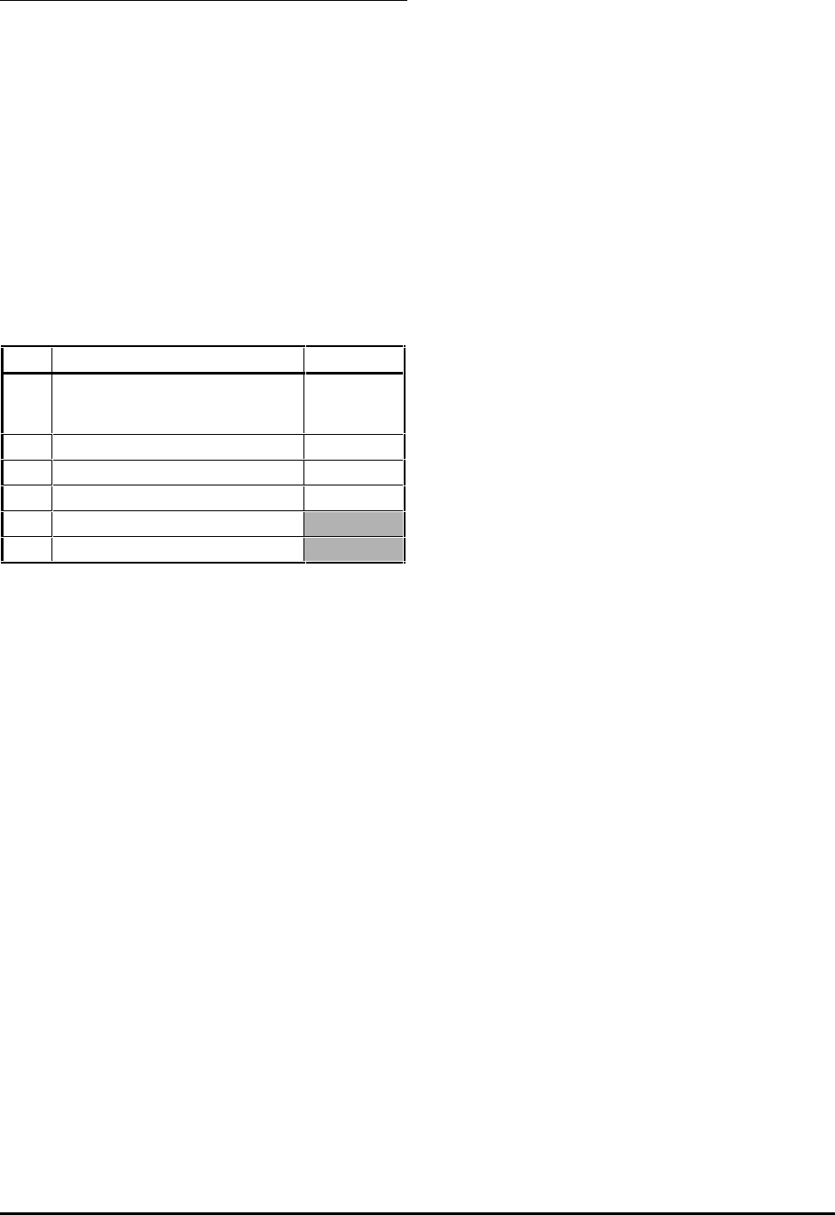
Reference selection
Use 0.05 Reference selector to select the required
frequency reference source, as follows:
0.05 Source Terminal(s)
0 Analog input 1 or 2 which can be
selected using the LOCAL/REMOTE
contact
5 and 6, or 7
1 Analog input 1 5, 6
2 Analog input 2 7
3 Preset frequencies
4 Keypad control
5 ( Do not use)
Analog input mode
The analog inputs are configured for 0 ~ 10V.
See the Commander Gp Advanced User Guide for
selecting other modes.
Brake-control settings
1. The default setting of 10% for parameter 0.19
Current threshold is suitable for the majority of
applications. If required, change the value to
the required percentage of I
max
(see below).
This value must ensure that adequate current
will flow through the motor to control the load
when the brake is released.
I
MAX
= FLC x 150%
2. If required, change the setting of 0.20 Brake
release delay to a suitable value (between 0 and
25 seconds) that will ensure a brake release
signal is not issued if the following occur
simultaneously under transient conditions:
• 0.16 Drive healthy indicator changes state
to 1
• 0.17 At zero speed changes state to 0
Braking mode
The FASt ramp mode is applied. This gives
continuous deceleration under maximum braking
conditions (the ramp mode should not be changed).
A braking resistor is normally required in order to
prevent the
DC-bus voltage from reaching the trip
level.
Stopping mode
The stopping mode is Ramp to a stop.


