12
NOTE: DIAGRAMS & ILLUSTRATIONS ARE NOT TO SCALE.
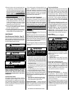
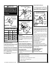
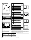
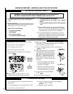
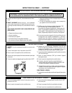
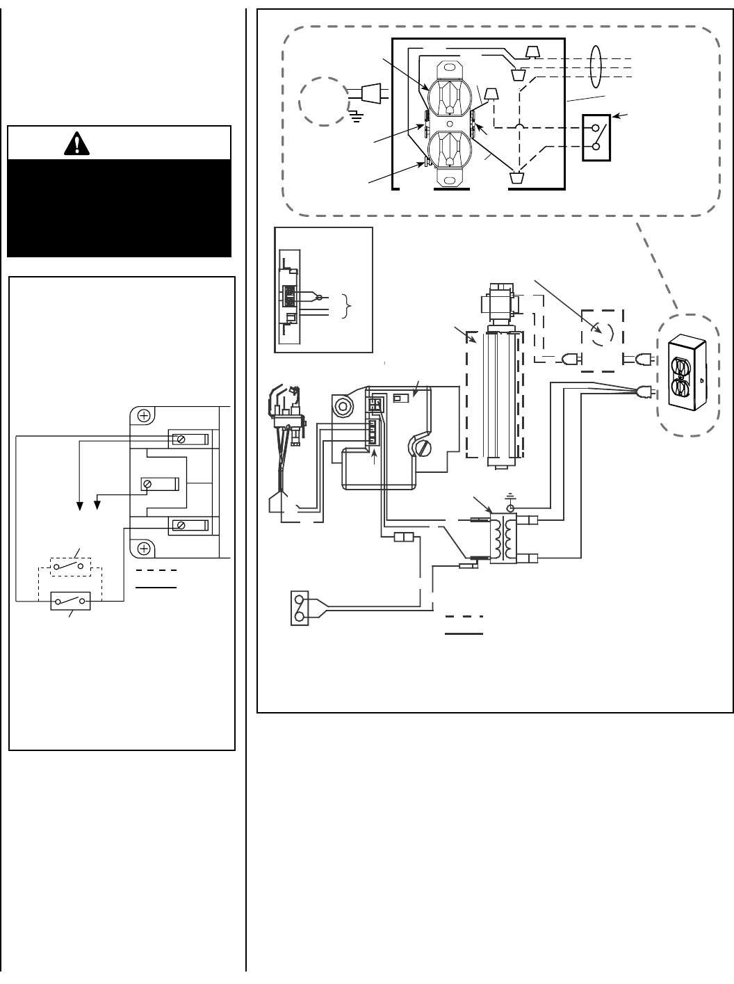
WIRING DIAGRAMS
Wiring diagrams are provided here for refer-
ence purposes only. This information is also
provided on schematics attached directly to the
appliance on a pullout panel located within the
control compartment.
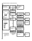
Thermopile
If any of the original wire as supplied must
be replaced, it must be replaced with Type
AWM 105
o
C - 18 gage wire.
* Optional Kits Installed - OFF/ON wall switch,
wall thermostat or remote control receiver.
Note: Turn the appliance-mounted OFF/ON
burner control switch to the OFF position if
any of these kits are installed.
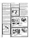
Millivolt Wiring Diagram
Schematic Representation Only
Field Wired
Factory
Wired
*Optional Switch
Standard OFF/ON Switch
CAUTION
Label all wires prior to discon-
nection when servicing con-
trols. Wiring errors can cause
improper and dangerous appli-
ance operation.
Figure 16
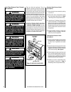
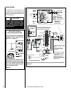
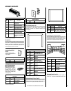
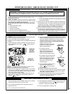
Figure 17
Electronic Wiring Diagram (Honeywell) Showing Blower Wiring for Optional FBK-100, FBK-200 & FBK-250 Kits
Schematic Representation Only
Relay Module C/W FBK-250 only. Plug blower
into J-Box receptacle for FBK-100 or FBK-200
application. See View A for J-Box wiring.
Optional Blower
*OFF/ON Switch
(Integral with
Gas Valve)
Honeywell
Electronic
Gas
Valve
120 VAC
Primary
Secondary
Optional Control Switch
Junction Box
Pilot Burner
Assembly
BL
BL
Field Wired
Factory
Wired
BK = BLACK BL = BLUE
R = RED W = WHITE
G = GREEN
BK
W
BK
BK
BL
R
GROUND
24 V
Transformer
View A
J-Box Wiring when
using unit mounted
relay module.
BK
W
G
C
AV
02
1
Igniter
Connector
* Leave the OFF/ON switch, which is
integral with the gas valve, in the ON
position.
**Optional Control Switches: Wall
Switch, Wall Thermostat or Remote
Control Receiver.
Notes:
1. If any of the original wire as supplied
must be replaced, use Type AWM 105°C
- 18 gage wire ONLY.
2. 120 VAC, 60 Hz - Less than 3 Amps.
Caution: label all wires prior to
disconnection when servicing controls.
Wiring errors can cause improper and
dangerous operation.
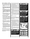
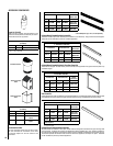
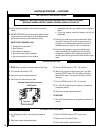
Junction Box
Tab Intact
Tab
Broken
Plug blower
into this
receptacle
n
e
e
r
G
-
dn
u
o
r
G
* Wall-mounted
ON/ OFF Blower
Switch or Variable
Speed Control Switch.
Blower
Ground
e
ti
h
W
-
lar
t
u
e
N
120 VAC - Black
Green
Ground
Screw
White
Green
Neutral
Side of
Receptacle
Hot
Side of
Receptacle
Red
Black
J-BOX WIRING FOR
WALL SWITCH
BLOWER CONTROL