No. 99MBC094A
1-2
1.3 Inspection and Maintenance
This section describes the inspection and maintenance procedures of the measuring unit.
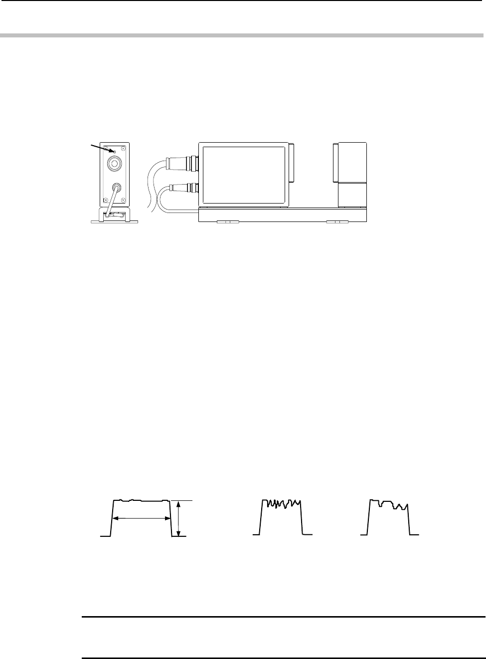
1.3.1 Laser emission display LED
The Laser Emission Display LED that is provided on the rear side lights while the laser
is being emitted to call the operator’s attention for safety. Do not look the laser beam.
1.3.2 Cleaning optical parts
To clean the optical parts, turn off the power switch and disconnect the signal cable for
safety.
Always keep the protective glass of the emission unit and reception unit clean. Soiled
protective glass will not only result in reduced measurement accuracy, but possibly
produce erroneous measurements due to dust and foreign particles being treated as part
of the workpiece.
For cleaning, use a blower brush or use gauze slightly dampened with ethyl alcohol to
gently wipe clean soiled portions using very light pressure.
z Checking the contamination of the protective glass using an oscilloscope
A monitor connector, “SCAN SIG.-1”, of the reception light signal is provided on the
rear panel of the display unit. Check the reception light signal by connecting the probe of
the oscilloscope with the monitor connector. Oscilloscope setup is as follows:
z Vertical sensitivity: 0.1V/DIV (with a probe of 10:1)
z Horizontal sensitivity: 100 µs/DIV
If the waveform generated by the oscilloscope looks like either of the ones shown in (b)
or (c), clean the protective glass to reduce the disorder of waveform to less than 0.3V.
NOTE
・The protective glass of the windows is a precision optical part. Handle with care so as
not to scratch the glass.
Laser emission
display LED
(c) Soiled glass
(b) Soiled glass
Approx.
4V
Approx.
310μS
(a) Normal


