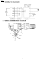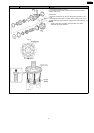
(Refer to WIRING CONNECTION DIAGRAM)
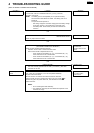
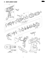
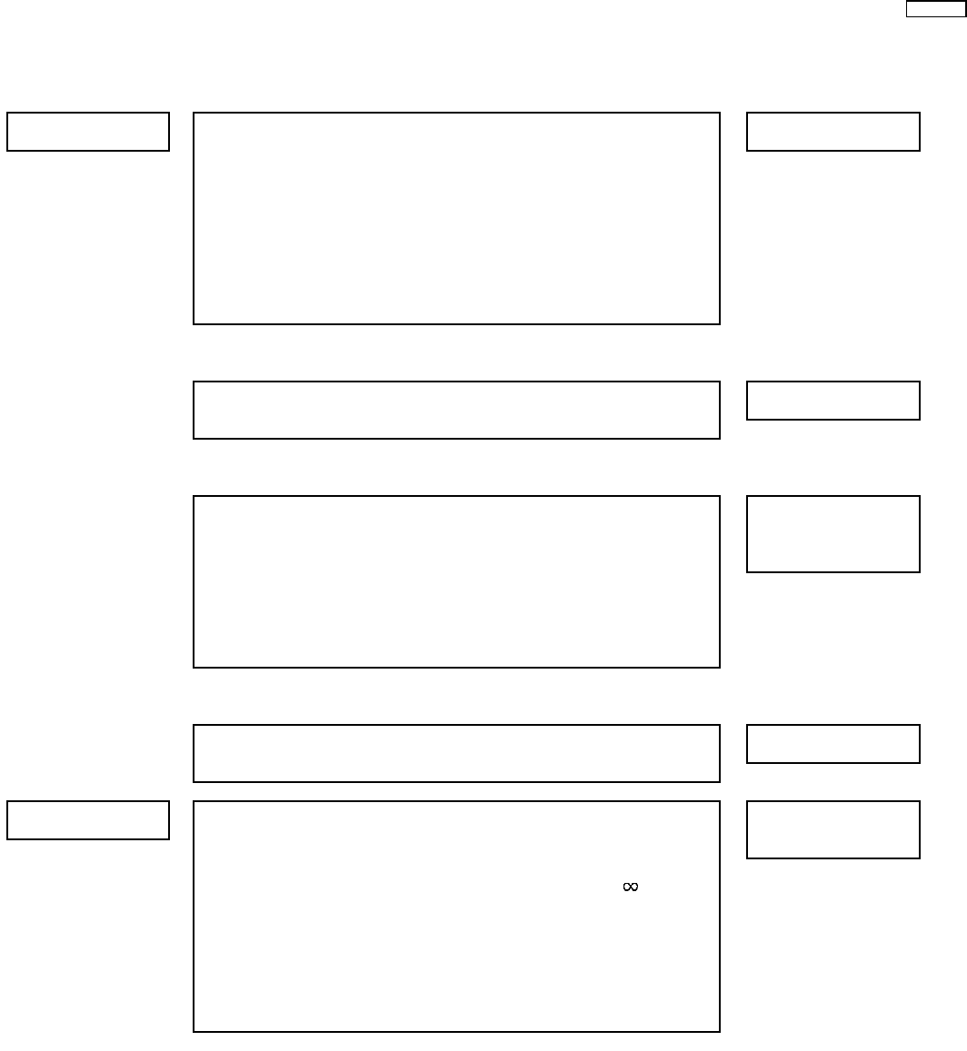
4 TROUBLESHOOTING GUIDE
< TROUBLE > < CHECK > < REMEDY >
Does not operate. <CHECK BATTERY PACK.> NO Replace battery pack.
→
If no less than 18V DC is available across the (+) and (-) terminals,
→
the battery pack is OK.
NOTE:
The battery pack is sold separately as an optional accessory.
See the nearest sales dealer for details. The battery pack has a
limited life.
The pack should be replaced if
- after being charged for the rated charging time the battery voltage
is less than 18V DC or the usable time is extremely short.
- the battery leaks. Check battery for leaks and terminals for
corrosion.
↓OK
<CHECK TERMINAL CONNECTIONS BETWEEN MAIN UNIT NO Repair contacts.
AND BATTERY PACK.>
→
Check for proper terminal contacts.
↓OK
<CHECK SWITCH BLOCK.> NO Contacts in switch block
(See WIRING CONNECTION DIAGRAM.)
→
are defective.
Check continuity between following terminals. Replace switch & FET
* Inspection of the forward / reverse selection switch. block.
When switch handle is depressed all the way:
- There should be 0Ω between (A) - (D) , and between (B) - (C) ;
when switch lever is set to forward side.
- There should be 0Ω between (A) - (C) , and between (B) - (D) ;
when switch lever is set to reverse side.
↓OK
<CHECK MOTOR.> NO Replace motor.
The motor normally operates with its white (+) and black (-) lead wires
→
connected to 18V DC.
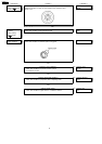
Does not speed- <CHECK FET.> NO Repair the contact
control. Even if FET block is defective, it can not be replaced individually.
→
or replace switch
Replace whole switch block. & FET block.
Remove the FET circuit block and check the lead wire terminals.
These terminals are open normally when there is an open circuit (
Ω)
between the green and yellow lead wires, and between the blue and
yellow lead wires.
NOTE:
* FET is weak against static electricity.
** The resistance value may be some differences depends on the
measurement range.
7
EY6950-U1