SERVICE AND ADJUSTMENTS
CAUTION: BEFORE PERFORMING ANYSERVICE OR ADJUSTMENTS:
Depress clutch/brake pedal fully and set parking brake.
Place gearshift lever in neutral (N) position.
• Place attachment clutch in "DISENGAGED" position.
• Turn ignition key "OFF" and remove key.
• Make sure the blades and all moving parts have completely stopped.
• Disconnect spark plug wire from spark plug and place wire where itcannot come in contact with
plug.
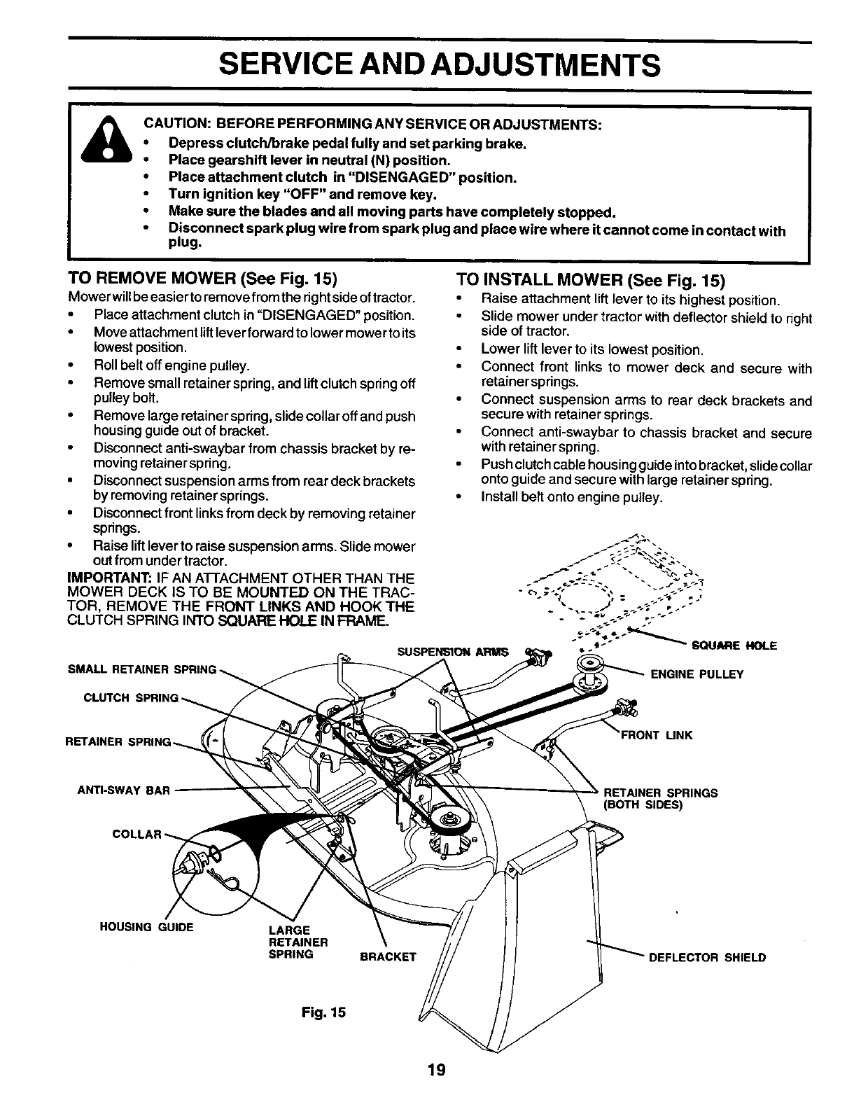
TO REMOVE MOWER (See Fig. 15)
Mower willbeeasier to remove fromthe rightside oftractor.
• Place attachment clutch in"DISENGAGED" position.
• Move attachment lift lever forward to lower mower to its
lowest position.
• Roll belt off engine pulley.
• Remove small retainer spring, and lift clutch spring off
pulley bolt.
• Remove large retainer spring, slide collar offand push
housingguide out of bracket.
• Disconnect anti-swaybar from chassis bracket by re-
moving retainer spring.
• Disconnect suspension arms from rear deck brackets
by removingretainer springs.
• Disconnect front linksfrom deck by removing retainer
springs.
• Raise liftlever to raise suspension arms. Slide mower
out from under tractor.
IMPORTANT: IF AN ATTACHMENT OTHER THAN THE
MOWER DECK IS TO BE MOUNTED ON THE TRAC-
TOR, REMOVE THE FRONT LINKS AND HOOK THE
CLUTCH SPRING INTO SQUARE HOLE IN FRAME.
SUSPENSION ARlUlS
TO INSTALL MOWER (See Fig. 15)
• Raise attachment lift lever to itshighest position.
Slide mower under tractor with deflector shield to right
side oftractor.
• Lower lift lever to its lowest position.
• Connect front links to mower deck and secure with
retainer springs.
• Connect suspension arms to rear deck brackets and
secure with retainer springs.
Connect anti-swaybar to chassis bracket and secure
with retainer spring.
• Pushclutchcable housingguide intobrecket,slide collar
onto guide and secure with large retainer spring.
• Install belt onto engine pulley.
SMALL RETAINER SPRING ENGINE PULLEY
CLUTCH
RETAINER :
FRONT LINK
ANTI-SWAY BAR
SPRINGS
(BOTH SIDES)
HOUSING GUIDE
LARGE
RETAINER
SPRING
BRACKET DEFLECTOR SHIELD
Fig. 15
19


