Chapter 3: Installation 21
• Where cables are fed through holes, always use grommets to prevent chafing.
• Secure long cable runs so they do not present a hazard.
• Do not route the cable through bilges.
• Wherever possible, route the cable away from fluorescent lights, engines,
radio transmitting equipment, as these may cause interference.
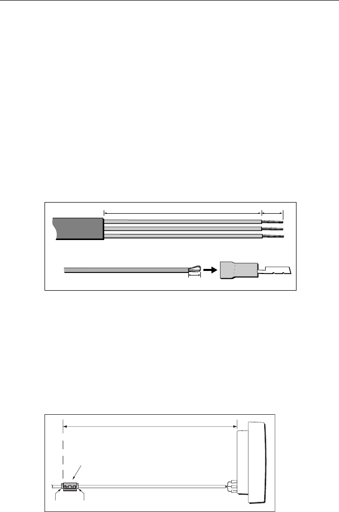
• Although the transducer cable is fitted with spade connectors for direct con-
nection to the rear of the instrument, it may be necessary to remove these to
facilitate installation, e.g. if the cable has to be routed through narrow aper-
tures. Extra spade connectors are provided, to replace any that are removed
when running the cable. When fitting spade connectors, prepare the cable as
at (a) in the following illustration, then fold back the wire strands and insert
into the spade connector as at (b). Ensure the wire strands do not extend
beyond the rear of the spade connector insulation, then crimp the connector
to the wire.
Fitting ferrite
Fit a suppression ferrite near the instrument end of the transducer cable, as
follows.
1. Release the catch on the ferrite, open it up then snap it closed around the
cable.
2. Position the ferrite as close as possible to the instrument end of the cable
(maximum 1 foot (300 mm) from the end) and fit a tie-wrap on the cable
either side of the ferrite, to hold it in position.
3 mm
6 mm
50 mm
(a)
(b)
D4467-6
Transducer cable
1 ft (300 mm) maximum
Ferrite
D4469-4
Tie-wraps
81038_4.book Page 21 Wednesday, March 24, 2004 3:17 PM
