Installation Instructions 11
Publication 1746-IN004B-EN-P - March 2008
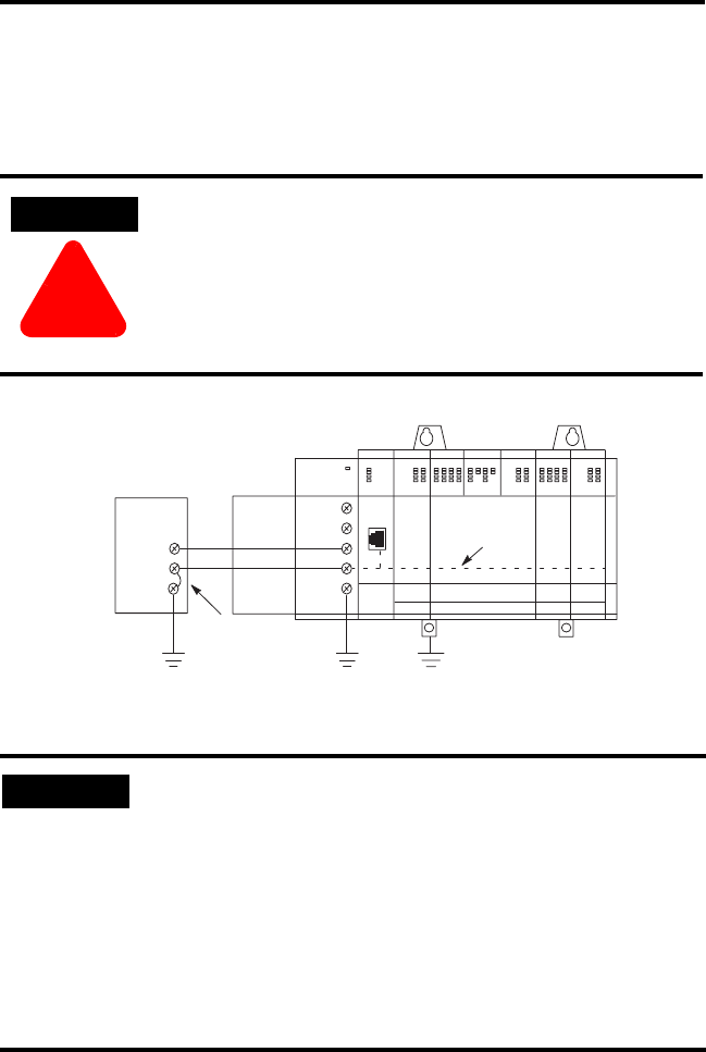
1746-P3 Wiring Considerations
This information describes special wiring considerations for the 1746-P3 power
supply that are not labeled as revision (REV) B.
ATTENTION
!
Any voltage applied to the 1746-P3 DC NEUT terminal will be
present at the SLC logic ground and the processor DH-485 port.
To prevent unwanted potentials across the logic ground of the
controller and/or damage to the SLC chassis, the DC NEUTRAL
terminal of the external DC power source must be either
isolated from the SLC chassis ground or connected to earth
ground as shown in the following illustration.
IMPORTANT
SLC 500 series A chassis (1746-A4, 1746-A7, 1746-A10, and
1746-A13) manufactured before November 1992 have a resistor
between the logic ground and chassis ground as the drawing on
the following page illustrates. This resistor could be damaged if
the wiring recommendation described within the attention box
above is not followed. See the figure on the following page for
the location of the resistor. SLC 500 series A chassis (1746-A4,
1746-A7, 1746-A10, and 1746-A13) with a manufacture date of
November 1992 or later do not have this resistor. SLC 500 series
B chassis have a 1 MΩ resistor that limits the current between
logic ground and chassis ground.
+24V dc
DC Neut
+24V dc
DC Neut
DH-485
Port
•
External DC Power Source
Door
1746-P3
Processor
SLC 500 Chassis
SLC Logic Ground
Chassis
Ground
Earth Ground
Earth
Ground
A jumper wire is
recommended between
the DC NEUT and Chassis
Ground of the external
power source.


