3
Sub-Frame Hitch Installation Instructions
A
F
C
D
G
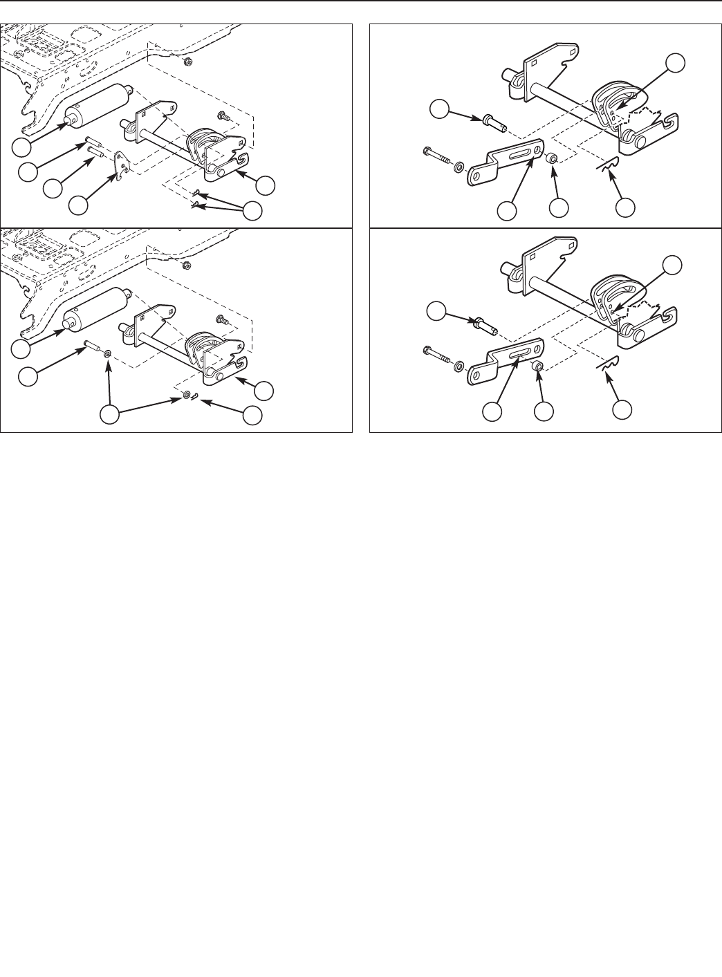
Figure 6. Lift Link - Manual Lift Models
A. Pin
B. Rear Hole of Lift Bar (Snowthrower/Dozer
Applications)
C. Spacer
D. Hair Pin Clip
E. Upper Hole (Snowthrower/Dozer Applications)
F. Slot of Lift Link (Mower Applications)
G. Lower Hole (Mower Applications)
A
B
C
D
E
Snowthrower
& Dozer
Applications
Mower
Applications
Figure 5. Lift Lock Plate - Hydraulic Lift Models
A. Lift Cylinder
B. Flat Head Pin (Original)
C. Flat Head Pin (New)
D. Lock Plate
E. Hair Pin Clips
F. Lift Shaft Assy.
G. Washers
A
B
C
D
F
E
A
B
F
G
E
Install Downward Pressure Lock
HYDRAULIC LIFT MODELS
1. Install the downward pressure lock plate (D, Figure 5)
and an additional pin (C). Note that the washers (G)
are not used with the lock plate.
MANUAL LIFT MODELS
NOTE: These instructions apply to Conquest / 1700 /
2700 Series tractors or Broadmoor / 1600 / 2600 Series
tractors equipped with a lift lever kit.
1. Install the lift link as shown in the upper frame of
Figure 6.
NOTE: The lift link on early model units had a hole locat-
ed in front of the slot, rather than behind. These early
model lift links must be removed and replaced with the
one contained in this kit (Ref. No. 22, Figure 1). The lift
link included with this kit (pictured above) is universal
and works in all applications.
Snowthrower
& Dozer
Applications
Mower
Applications