INSTALLATION | 23
PIN DESCRIPTION
5 Record Start 1
6 Ring Mute In 1
7 N/C
8 +5VDC (50mA max)
9 Record Stop 1
10 User Out (Dump) 2
11 Ringing Out 2
12 Priority Ringing Out 2
13 Ring Mute In 2
14 (reserved)
15 N/C
Note for the Curious
The DB- designation for D-Sub connectors is from Cinch Corp’s part numbering system. The
proper Cinch designation for a 15 pin D-Sub connector is a DA-15p (plug) or DA-15s (socket)
not DB-15! (Our thanks to Mike Schweizer, for contributing this tidbit.)
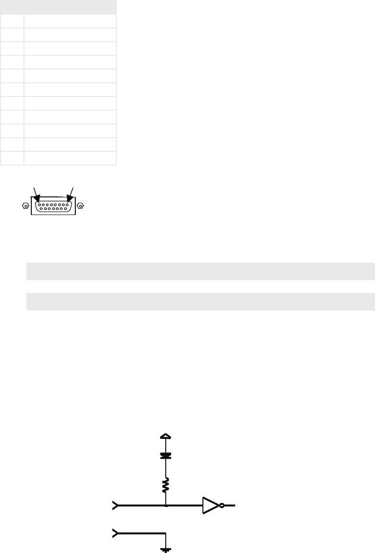
Input Characteristics
e NX12’s inputs are designed to be universal. ey accept either a voltage source up
♦
to 24VDC, or a closure to ground, which may be provided by switches, relays, or logic
outputs. In the latter case either ‘totem-pole’ or open-collector will work. e inputs are
active low.
A built in 1k Ohm pull up resistor is provided. ♦
Parallel logic input circuit:
Output Characteristics
Open collector to ground.
♦
ese will require a pull-up resistor to drive TTL-style logic inputs. Most equipment has ♦
the pull-up built into the input, but if there is no pull-up, you’ll have to add one, connect-


