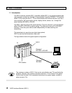
User’s Manual
25
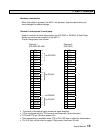
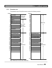
4. Register Configuration
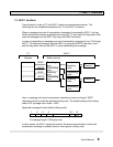
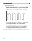
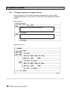
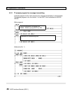
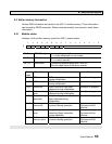
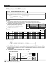
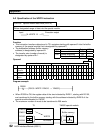
The following table shows the functions of I/O registers assigned to the AS311.
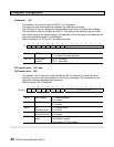
XW(n) CH1 status
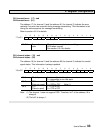
XW(n+1) CH2 status
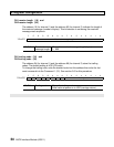
YW(n+2) CH1 command
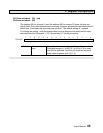
YW(n+3) CH2 command
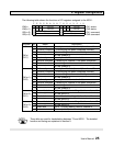
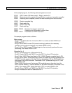
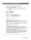
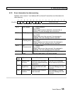
Register Bit Name Description
F Write ready 1: ready to write data (transmit) for channel 1
E Transmit complete 1: transmitting has been completed normally
D Transmit error 1: transmitting has been canceled by error
XW(n) C - 8 − No use (always 0)
(CH1) 7 Read ready 1: ready to read the received data
6 Receive complete 1: receiving for channel 1 has been completed
5 Receive error 1: receiving error has occurred
4 - 0 − No use (always 0)
F Write ready 1: ready to write data (transmit) for channel 2
E Transmit complete 1: transmitting has been completed normally
D Transmit error 1: transmitting has been canceled by error
XW(n+1) C - 8 − No use (always 0)
(CH2) 7 Read ready 1: ready to read the received data
6 Receive complete 1: receiving for channel 2 has been completed
5 Receive error 1: receiving error has occurred
4 - 0 − No use (always 0)
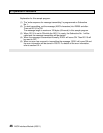
F Transmit start Set to 1 to start transmitting data from channel 1
YW(n+2) E - 8 − No use (set to 0)
(CH1) 7 Read start Set to 1 to start reading data for channel 1
6 - 0 − No use (set to 0)
F Transmit start Set to 1 to start transmitting data from channel 2
YW(n+3) E - 8 − No use (set to 0)
(CH2) 7 Read start Set to 1 to start reading data for channel 2
6 - 0 − No use (set to 0)
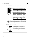
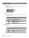
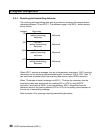
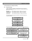
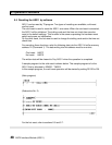
These bits are used for handshaking between T3 and AS311. The detailed
function and timing are explained in section 5.
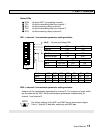
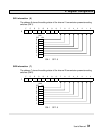
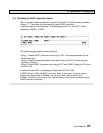
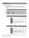
F E D C B A 9 8 7 6 5 4 3 2 1 0
No use No use
No use No use
No use No use
No use No use
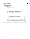
NOTE