


2 Issue 1, January 2004 61175043L3-5A
black cap to the left and pulling the fuse out. After the new
fuse is inserted, the cap is pushed back in and turned to the
right.
Status LED
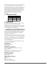
A single multi-feature LED on the front panel provides AC
operation or battery operation power status. Refer to Table 1
for indication descriptions.
3. INSTALLATION
SAFETY INFORMATION
When using your telephone equipment, please follow these
basic safety precautions to reduce the risk of fire, electrical
shock, or personal injury:
1. Do not use this product near water, such as a bathtub,
wash bowl, kitchen sink, laundry tub, in a wet basement,
or near a swimming pool.
2. Avoid using a telephone (other than a cordless-type)
during an electrical storm. There is a remote risk of
shock from lightning.
3. Do not use the telephone to report a gas leak in the
vicinity of the leak.
4. Use only the power cord, power supply, and/or batteries
indicated in the manual. Do not dispose of batteries in a
fire; they may explode. Check with local codes for spe-
cial disposal instructions.
ELECTROSTATIC INSTRUCTIONS
After unpacking the unit, inspect it for damage. If damage is
noted, file a claim with the carrier then notify ADTRAN
Customer Service.
MOUNTING AND WIRING INSTRUCTIONS
The following are mounting instructions for the AC/DC
PS/BC when utilized with some of the various ADTRAN
product systems. If your ADTRAN system is not listed in this
section, please refer to the documentation provided with your
ADTRAN product system for more detailed instructions.
Wallmounting
For the wallmount arrangement, the PS/BC is normally in-
stalled on the designated 3/4-inch or thicker plywood with
four #6 by 3/4-inch flat-head wood screws. Installation is as
follows:
1. Determine the preferred layout and ensure the socket-
outlet is located near the equipment and easily accessi-
ble.
2. Ensure the unit is plumb, then mark through the four
screw holes to identify where the pilot holes will be
drilled.
3. Using a 1/16-inch bit, drill pilot holes at the marked
locations.
4. Mount the unit using the pan-head screws.
5. Route and connect all cabling to the appropriate device.
Use cable tie-downs as needed.
6. Connect the ground stud using the most direct route to a
known equipment ground source.
Total Access 750/850
Mounting
Position the Total Access PSU (power cords oriented down-
ward) and align all four holes (on the tabs at the corner of the
Total Access PSU) with the four available machined holes on
either side of the Total Access 750/850. Use four #6 3/8-inch
machine screws (provided) to secure the Total Access PSU.
Alternately, the Total Access PSU can be mounted to a back-
board with four #6 3/4-inch wood screws (not supplied).
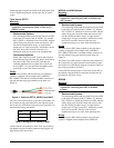
Wiring
The Total Access PSU has two cords (AC plug and 4 position
modular adapter). Insert the Total Access PSU modular
Table 1. LED Indication
AC Power Operation Battery Operation
Green OK Green OK (charging)
Yellow Power Fail Yellow Discharging
Red Power Fail Red Low (< 40V)
Off Power Fail Off Disconnected
CAUTION
This equipment MUST only be installed in a DC-C
bonding and grounding environment per Telcordia
GR-1089-CORE, Issue 3. It may not be utilized in a
DC-I (isolated) bonding and grounding environment.
CAUTION
Electronic equipment can be damaged by static
electrical discharge. Before handling equipment, wear
an antistatic discharge wrist strap to prevent damage
to electronic components. Place equipment in
antistatic packing material when transporting or
storing. When working on equipment, always place
them on an approved antistatic mat that is
electronically grounded.
C A U T I O N
C A U T I O N
!
SUBJECT TO ELECTROSTATIC DAMAGE
OR DECREASE IN RELIABILITY.
HANDLING PRECAUTIONS REQUIRED.
Mount the power supply on the left side of the Total
Access 750/850 shelf (next to the battery cover hinge)
for battery backup installations (P/N 1175044L2 and
1175044L4)
Before beginning the wiring connection, verify that the
Total Access 750/850 and the AC/DC Power Supply
and Battery Charger are properly grounded with the
required supplemental ground.
Power should be the last connection made during
installation.