


61175043L3-5A Issue 1, January 2004 3
adapter into the receptacle provided on the back of the Total
Access 750/850 and plug the AC plug into the AC power
source.
Total Access OPTI-3
Mounting
Rackmounted Systems
Use a mounting bracket and secure the Total Access PSU
to the rack (19” bracket–P/N 1175050L1, 23” bracket–
P/N 1175051L1). Orient the Total Access PSU with the
cables facing away from the center and secure it with
four #6 3/8-inch machine screws. A single bracket
mounts up to 4 Total Access PSUs. Alternately, mount
the Total Access PSU directly to the rack (or a
backboard) using two or more of the mounting tabs.
Wallmounted Systems
Position the Total Access PSU (power cords oriented
downward) and align the outer two holes (on the tabs at
the corner of the Total Access PSU) with the two
available machined holes on either side of the Total
Access OPTI-3. Use two #6 3/8-inch machine screws
(provided) to secure the Total Access PSU.
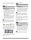
Wiring
The Total Access PSU (when ordered for use with these
systems) is shipped with an adapter cable (ADTRAN
P/N 1200657L10) that has a molded modular connector on
one end and three ring type terminals on the other (see
Figure 2).
Figure 2. Cable for OPTI-3, MX2810, and NIU3
The Total Access PSU powers a single bus (select either A or
B). Connect the ring-type terminals to the respective termi-
nals on the rear of the chassis using the screws provided. Use
the following wiring conventions:
Connect the DC wiring harness of the Total Access PSU to
the adapter using the modular connectors and plug the AC
plug into the AC power source.
MX2810 and NIU3 Systems
Mounting
Rackmounted Systems
Use a mounting bracket and secure the Total Access PSU
to the rack (19” bracket–P/N 1175050L1, 23” bracket–
P/N 1175051L1). Orient the Total Access PSU with the
cables facing away from the center and secure it with
four #6 3/8-inch machine screws. A single bracket
mounts up to 4 Total Access PSUs. Alternately, mount
the Total Access PSU directly to the rack (or a
backboard) using two or more of the mounting tabs.
Wiring
The Total Access PSU (when ordered for use with these
systems) is shipped with an adapter cable (ADTRAN
P/N 1200657L10) that has a molded modular connector on
one end and three ring type terminals on the other (see
Figure 2).
The Total Access PSU powers a single bus (select either A or
B). Connect the ring-type terminals to the respective termi-
nals on the rear of the chassis using the screws provided. Use
the wiring conventions in Table 2.
Connect the DC wiring harness of the Total Access PSU to
the adapter using the modular connectors and plug the AC
plug into the AC power source.
MX2800
Mounting
Rackmounted Systems
Use a mounting bracket and secure the Total Access PSU
to the rack (19” bracket–P/N 1175050L1, 23” bracket–
P/N 1175051L1). Orient the Total Access PSU with the
cables facing away from the center and secure it with
four #6 3/8-inch machine screws. A single bracket
mounts up to 4 Total Access PSUs. Alternately, mount
the Total Access PSU directly to the rack (or a
backboard) using two or more of the mounting tabs.
Wiring
The Total Access PSU (when ordered for use with this
system) is shipped with an adapter cable (ADTRAN
An additional cable (ADTRAN P/N 1200657L10) is
required for connecting the PS/BC to Total Access
OPTI-3 systems.
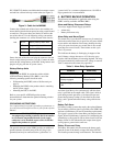
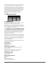
RED -48VA or PWR
BLACK RET
GREEN Ground Terminal
Table 2. Wiring (OPTI-3, MX2810, NIU3)
An additional cable (ADTRAN P/N 1200657L10) is
required for connecting the PS/BC to MX2810 and
NIU3 systems.
An additional cable (ADTRAN P/N 1200657L2) is
required for connecting the PS/BC to MX2800
systems.