


PCA-9372 User’s Manual 14
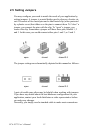
3. Press the DIMM module right down into the socket, until you hear
a click. This is when the two handles have automatically locked the
memory module into the correct position of the socket.
To remove the memory module, just push both handles outward, and the
module will be ejected from the socket.
2.8 IDE, CDROM hard drive connector (CN13)
The PCM-9372 provides 1 IDE channels which you can attach up to two
Enhanced Integrated Device Electronics hard disk drives or CDROM to
the PCM-9372’s internal controller. The PCM-9372's IDE controller uses
a PCI interface. This advanced IDE controller supports faster data trans-
fer, PID mode 3, mode 4 and up to UDMA/100.
2.8.1 Connecting the hard drive
Connecting drives is done in a daisy-chain fashion. This package includes
1 40PIN IDE cable that can connect to 3.5"HDD and CD ROM device.
1.8" and 2.5" drives need a 1 x 44-pin to 2 x 44-pin flat-cable connector
(p/n: 1701440500).
1. Connect one end of the cable to CN13. Make sure that the red (or
blue) wire corresponds to pin 1 on the connector, which is labeled
on the board (on the right side).
2. Plug the other end of the cable into the Enhanced IDE hard drive,
with pin 1 on the cable corresponding to pin 1 on the hard drive.
(See your hard drive’s documentation for the location of the con-
nector.)
If desired, connect a second drive as described above.
Unlike floppy drives, IDE hard drives can connect to either end of the
cable. If you install two drives, you will need to set one as the master and
one as the slave by using jumpers on the drives. If you install only one
drive, set it as the master.
2.9 Solid State Disk
The PCM-9372 provides a CompactFlash™ card socket and DiskOnChip
socket for Solid state disk solutions.
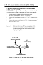
2.9.1 CompactFlash (CN21)
The CompactFlash card shares a secondary IDE channel which can be
enabled/disabled via the BIOS settings.