


v
Contents
Chapter 1 Introduction ......................................................2
1.1 Introduction ....................................................................... 2
1.1.1 Highly integrated multimedia SBC................................. 2
1.2 Features ............................................................................. 3
1.3 Specifications .................................................................... 3
1.3.1 Standard 3.5" Biscuit SBC Functions............................. 3
1.3.2 VGA/LCD Interface ....................................................... 4
1.3.3 Ethernet Interface............................................................ 4
1.3.4 Audio Function ............................................................... 4
1.3.5 Mechanical and Environmental ...................................... 4
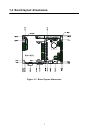
1.4 Board layout: dimensions.................................................. 5
Chapter 2 Installation ........................................................8
2.1 Jumpers.............................................................................. 8
Table 2.1:Jumpers........................................................... 8
2.2 Connectors......................................................................... 8
Table 2.2:Connectors...................................................... 8
2.3 Locating jumpers............................................................. 10
Figure 2.1:Jumper locations.......................................... 10
2.4 Locating Connectors ....................................................... 11
Figure 2.2:Connectors (component side)...................... 11
2.5 Setting Jumpers ............................................................... 12
2.6 Clear CMOS (S2)............................................................ 13
Table 2.3:CMOS clear (S2) .......................................... 13
2.7 Installing DIMMs............................................................ 13
2.8 IDE, CDROM hard drive connector (CN13) .................. 14
2.8.1 Connecting the hard drive............................................. 14
2.9 Solid State Disk............................................................... 14
2.9.1 CompactFlash (CN21) .................................................. 14
2.10 Floppy drive connector (CN20) ...................................... 15
2.10.1 Connecting the floppy drive ......................................... 15
2.11 Parallel port connector (CN19) ....................................... 15
2.12 Keyboard and PS/2 mouse connector (CN12) ................ 16
2.13 Power & HDD LED, Reset Button Connector
(CN11, S1) ...................................................................... 16
2.13.1 Power & HDD LED (CN11) ........................................ 16
2.13.2 Reset switch (S1) .......................................................... 16
2.14 Power connectors (CN9, CN10, CN22).......................... 16
2.14.1 Peripheral power connector, -5 V, -12 V (CN10)....... 16
2.14.2 Main power connector, +5 V, +12 V (CN9)................ 16
2.14.3 CPU Fan power supply connector (CN22)................... 16