Status Reporting 55
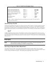
Table 4-4. Default Power On Register States
Register
Condition Caused By
Operation PTR; Questionable PTR All bits = 1
STAT:PRE
Operation NTR; Questionable NTR All bits = 0
STAT:PRE
Operation Event; Questionable Event All bits = 0
*CLS
Operation Enable; Questionable Enable All bits = 0
STAT:PRE
Standard Event Status Enable All bits = 0
1
*ESE 0
Status Byte All bits = 0
*CLS
Status Request Enable All bits = 0
1
*SRE 0
Output Queue Cleared
*CLS
1
If PSC=1. If PSC = 0, then the last previous state before turn on is recalled. The value of PSC is
stored in nonvolatile memory.
The PON (Power-On) Bit
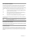
The PON bit in the Standard Event register is set whenever the power supply is turned on. The most common use for PON
is to generate an SRQ at power on following an unexpected loss of power. To do this, bit 7 of the Standard Event Enable
register must be set so that a power-on event registers in the ESB (Standard Event Summary Bit). Also, bit 5 of the Service
Request Enable register must be set to permit an SRQ to be generated. The commands to accomplish these two conditions
are:
*ESE 128
*SRE 32
If *PSC is programmed to 0, the contents of the Standard Event Enable and Service RequestEnable registers are saved in
nonvolatile memory and recalled at power on. This allows a PON event to generate SRQ at power on. Programming *PSC
to 1 prevents these registers from being saved and they are cleared at power on. This prevents a PON event from generating
SRQ at power on.
Examples
Note These examples are generic SCPI commands. See "Chapter 2 - Remote Programming" for
information about encoding the commands as language strings.
Servicing an Operation Status Mode Event
This example assumes you want a service request generated whenever the power supply switches to the CC (constant
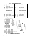
current) mode. From Figure 4-1, note that the required path is for a condition at bit 10 (CC) of the Operation Status register
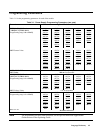
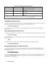
to set bit 6 (RQS) of the Status Byte register. The required register programming is shown in Table 4-5.


